VAG 1K0501529F ARM SUB-ASSY
Product Specifications
| VAG | 1K0501529F |
| VAG | 1K0501529E |
| VAG | 1K0501529J |
| VAG | 2H0407077A |
| VAG | 1K0501541C |
| VAG | M112919470 |
| VAG | M112919460 |
| VAG | 1K0505543A |
| VAG | 1K0505185B |
| LYNXAUTO | C5032L |
| MILES | DB61010 |
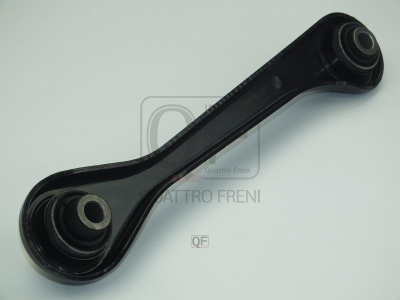
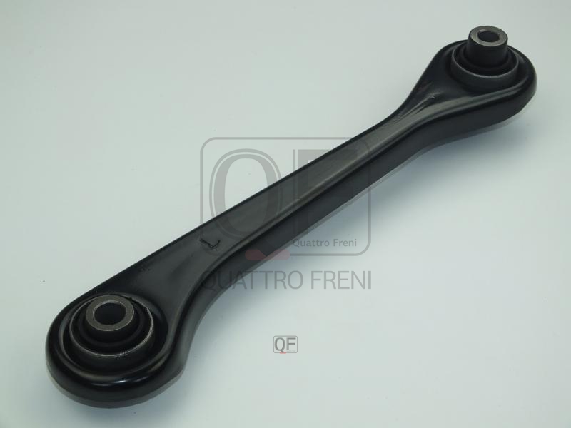
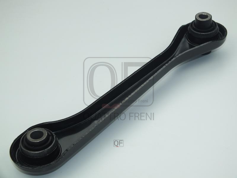
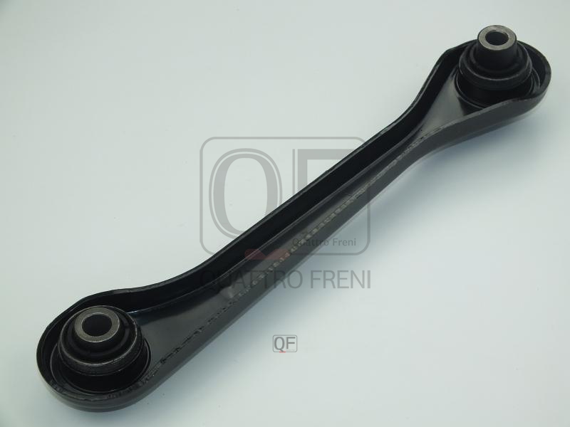
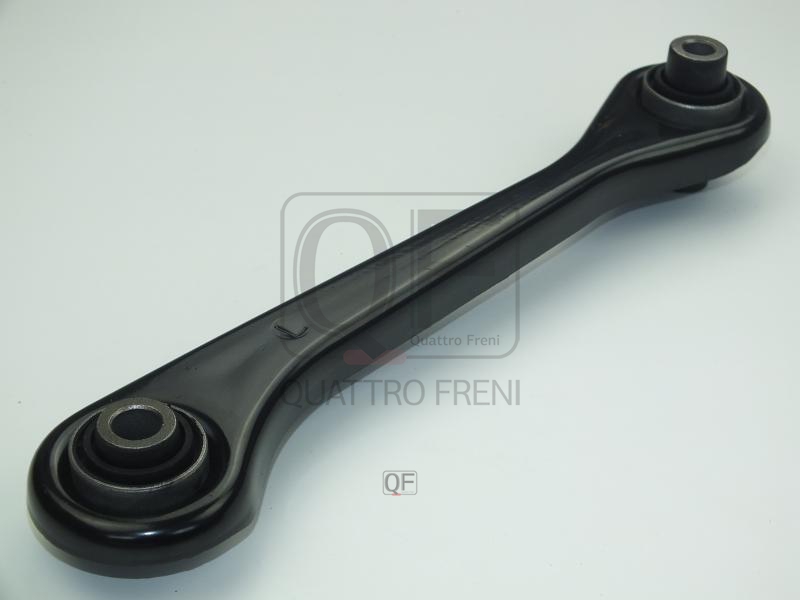
The ARM SUB-ASSY is a structural steel or aluminium forging that forms the primary kinematic link between the wheel hub carrier and the vehicle subframe or body, defining the wheel's position in space through its full range of suspension travel. Depending on position in the suspension geometry, the arm controls camber angle, toe, caster, and scrub radius — parameters that directly determine tyre wear, straight-line stability, and cornering behaviour. Lower control arms on MacPherson strut suspensions carry the full vertical load of the wheel assembly; rear lateral arms on multi-link suspensions define toe and camber under dynamic loading. Ball joints and rubber or polyurethane bushings at each end of the arm provide controlled compliance while isolating road noise and vibration from the cabin.
This unit — VAG 1K0501529F — is manufactured to OEM-equivalent specifications: arm geometry and section profile, ball joint stud taper and articulation angle, bushing inner and outer diameter and durometer, and overall load rating are matched to the original part. Supplied as a direct bolt-in replacement for standard fitment. Available wholesale from 4.42 USD, MOQ 50 pcs, production lead time 33 days.
Control arm failure is almost always progressive — the rubber bushings at the subframe end oxidise and crack with age and oil contamination, developing play before the arm body itself is affected. A worn bushing produces knocking under braking and acceleration torque and causes the wheel alignment to shift dynamically under load, producing uneven tyre wear and steering wander. Inspect the arm by gripping it and attempting to move it in all directions with the wheel raised — any free movement beyond the designed compliance of the bushing indicates replacement is required. Always have wheel alignment checked after fitting a new arm.
- Raise and support the vehicle on axle stands and remove the wheel. Apply penetrating oil to all arm mounting bolts and ball joint nuts at least 15 minutes before attempting removal — subframe bolts on high-mileage vehicles are frequently severely corroded and require extended soak time.
- Support the hub carrier with a hydraulic jack under the hub before disconnecting the arm — without support the hub will drop to full droop when the arm is removed, stressing the brake hose, ABS cable, and CV joint.
- Disconnect the ball joint at the hub carrier by removing the pinch bolt or castle nut and using a ball joint separator tool — never strike the hub carrier directly to release the taper. On arms with an integrated ball joint, the entire arm is removed as one assembly.
- Remove the subframe mounting bolts and extract the arm. Note the exact position of any eccentric washers or offset bolts used for camber or toe adjustment — photograph before removal and return them to the same position on reassembly as a starting point for alignment.
- Compare the new arm to the old unit before installation — verify arm length, bushing bore diameters, ball joint taper, and bolt hole positions. On vehicles with separately replaceable bushings, confirm whether the new arm is supplied complete or requires bushing transfer.
- Install the new ARM SUB-ASSY (VAG 1K0501529F), start all bolts by hand, torque subframe bolts with the suspension at ride height rather than full droop to avoid pre-loading the bushings, torque the ball joint to OEM specification, refit the wheel, and have the wheel alignment set immediately — the vehicle must not be driven on public roads until alignment is confirmed.