VAG 02T141153F CYLINDER CLUTCH
Product Specifications
| VAG | 02T141153F |
| VAG | 02T141153G |
| VAG | 02T141153Q |
| VAG | 02T141170B |
| VAG | 04E141015J |
| VAG | 02T141153 |
| MILES | GE16026 |
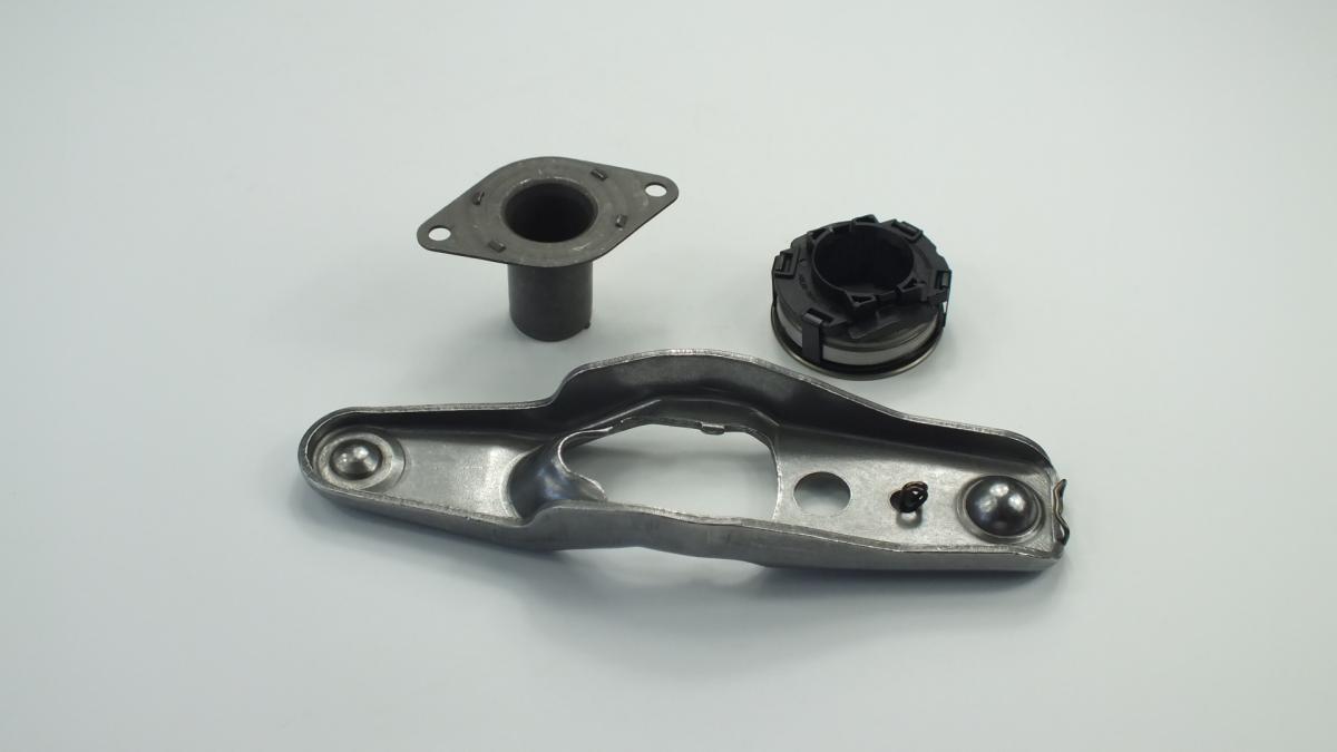
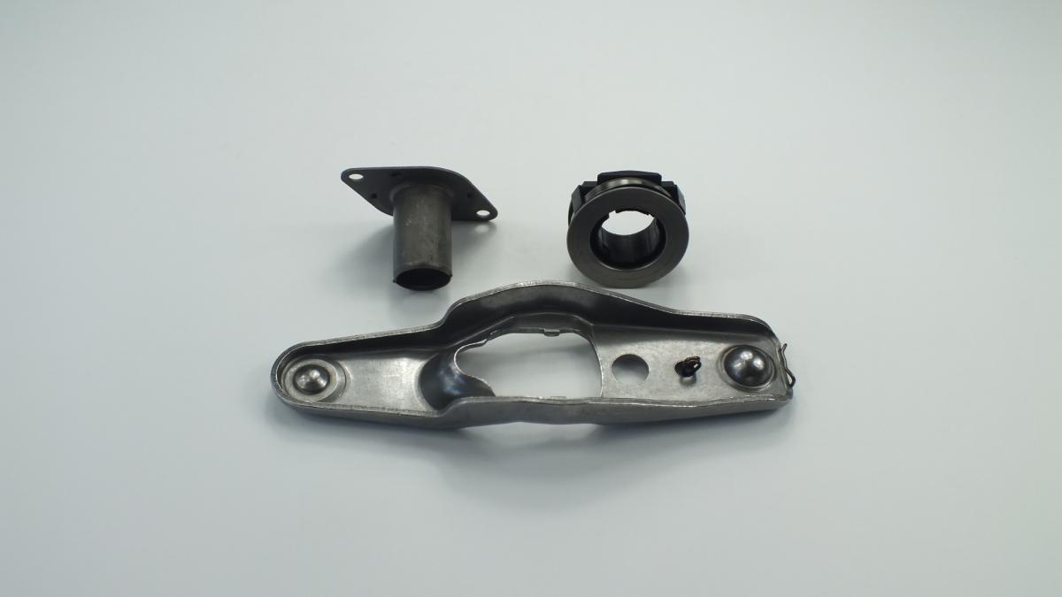
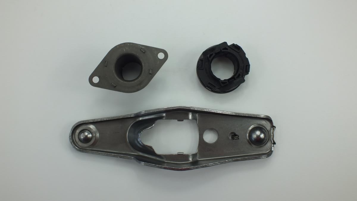
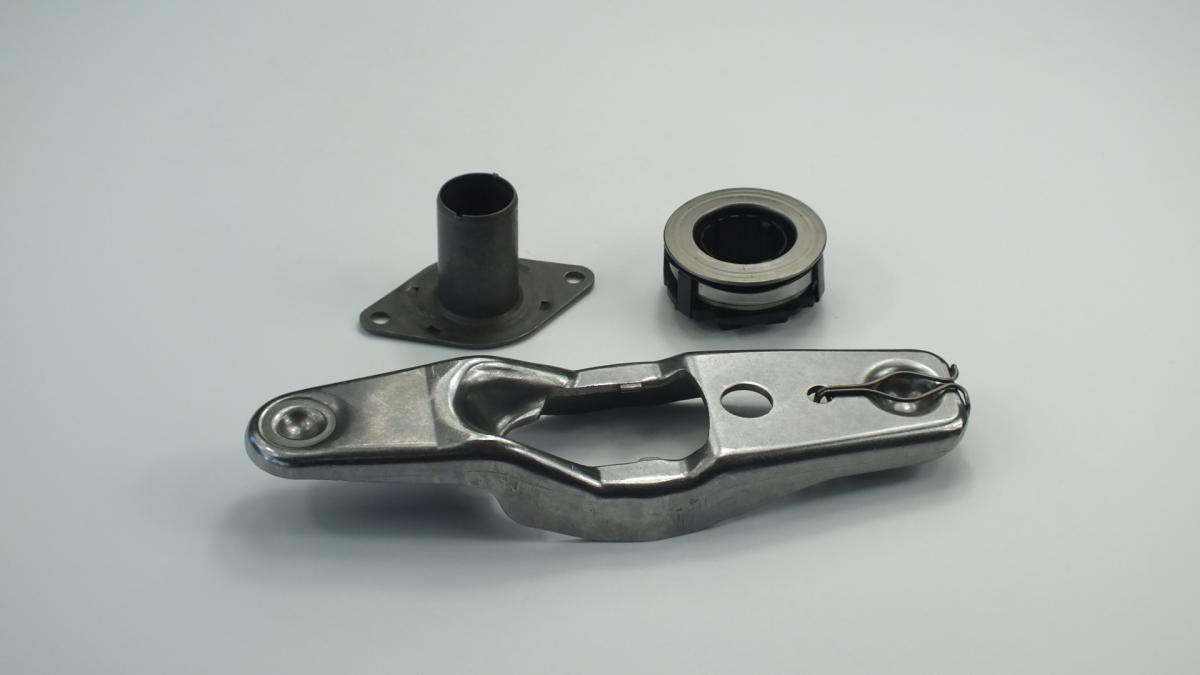
The CYLINDER CLUTCH is the clutch release bearing — also termed the throw-out bearing — that transmits the axial load from the stationary clutch fork or concentric slave cylinder to the rotating diaphragm spring fingers of the pressure plate assembly, compressing the diaphragm spring to release the clamping force on the clutch disc and disengage the drivetrain from the engine during gear changes. The bearing consists of a deep-groove angular-contact ball bearing with a hardened steel thrust face on one side that contacts the diaphragm spring fingers and a mounting collar on the other side that slides on the transmission input shaft sleeve or clips onto the concentric slave cylinder piston. Unlike most vehicle bearings which operate intermittently under load, the release bearing on vehicles with a continuous-contact clutch pedal design rotates at engine speed at all times — it is permanently engaged against the diaphragm spring fingers with a light preload — and is therefore subject to continuous fatigue loading throughout the engine's running life. On vehicles with a touch-type or free-play clutch design the bearing contacts the diaphragm fingers only when the clutch pedal is depressed, giving it a lower duty cycle but subjecting it to higher intermittent loads at each engagement.
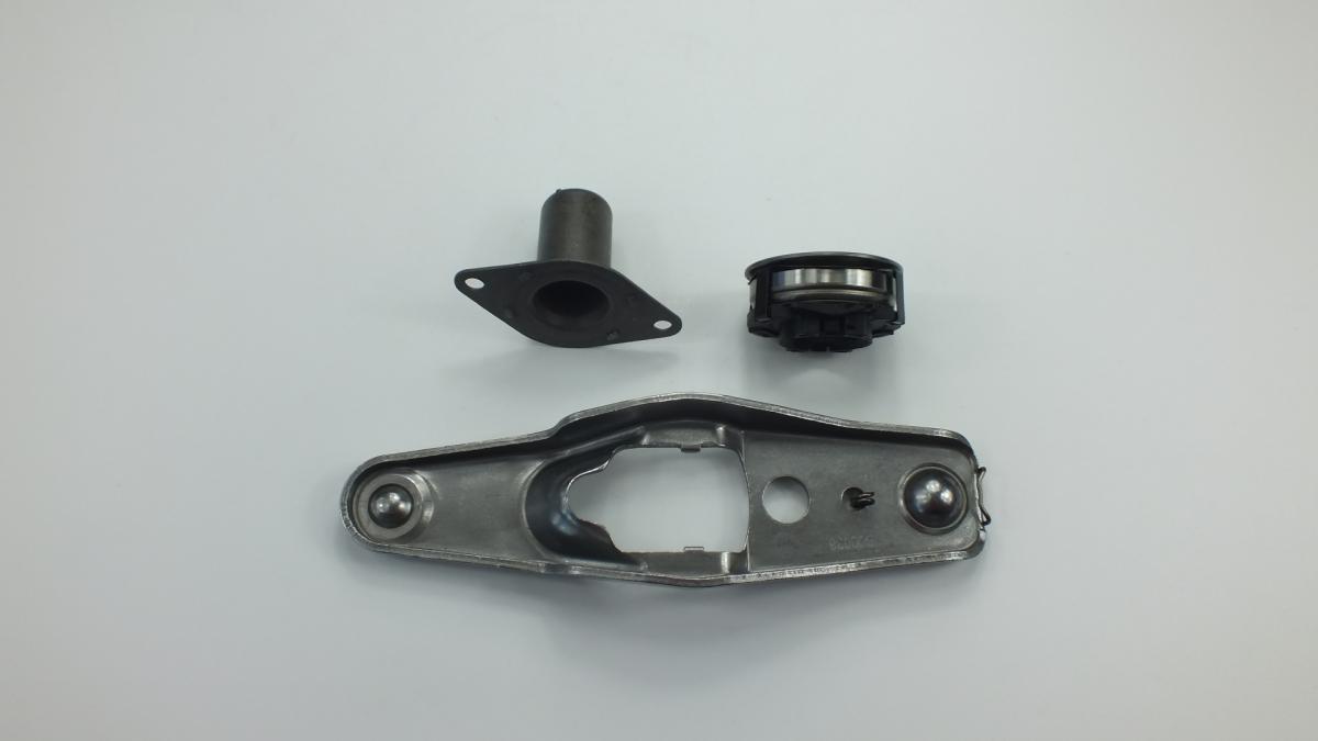
This unit — VAG 02T141153F — is manufactured to OEM-equivalent specifications: bearing dynamic load rating and static thrust capacity, thrust face outer diameter to match the diaphragm spring finger pattern, collar bore diameter and guide sleeve fit, overall axial height, and mounting clip or retainer geometry are matched to the original part. Supplied as a direct replacement for standard fitment. Available wholesale from 5.48 USD, MOQ 50 pcs, production lead time 46 days.
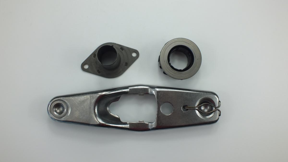
Release bearings fail through grease exhaustion from the bearing's sealed grease pack after high-mileage continuous rotation, raceway fatigue pitting from repeated high-load engagement cycles on vehicles used frequently in heavy traffic or with a driver habit of resting a foot on the clutch pedal under load, and collar guide wear from insufficient lubrication of the input shaft sleeve contact surface. The release bearing is only accessible after transmission removal — always replace it as part of every clutch service regardless of its apparent condition, as the incremental cost of the bearing is negligible relative to the labour cost of returning to replace it if it fails shortly after the clutch disc and pressure plate have been renewed.
- Support the transmission independently on a transmission jack before unbolting it from the engine — a transmission weighing 40–80 kg will drop immediately when the last bellhousing bolt is removed; support it at its centre of gravity and lower it slowly, guiding the input shaft clear of the clutch disc hub spline to avoid bending the disc damper springs or fouling the release bearing collar on the guide sleeve.
- Inspect the input shaft guide sleeve for wear grooves and corrosion before fitting the new bearing — the release bearing collar slides on this sleeve throughout its travel; a grooved or corroded sleeve prevents smooth bearing travel, causing incomplete clutch disengagement and premature collar wear on the new bearing; clean the sleeve with fine abrasive cloth and apply a light film of high-melting-point grease to the sleeve surface.
- Do not apply grease to the diaphragm spring finger tips or the bearing thrust face — grease contamination of the finger tips migrates onto the clutch disc friction surface under centrifugal force, causing immediate clutch slip; apply grease only to the input shaft sleeve and the clutch fork pivot ball where specified by the OEM.
- Confirm the new bearing collar clips or slides correctly onto the clutch fork arms or concentric slave cylinder piston before refitting the transmission — a bearing that is not positively retained on the fork will disengage from the fork on the first clutch release event, jamming between the fork and bellhousing wall and preventing any further clutch operation.
- Align the clutch disc concentrically using a clutch alignment tool before inserting the transmission input shaft — an off-centre disc will prevent the input shaft from entering the pilot bearing in the crankshaft end; forcing the shaft into a misaligned disc bends the disc hub spline and destroys the new disc before the transmission is fully installed.
- Install the new CYLINDER CLUTCH (VAG 02T141153F), reinstall the transmission, torque all bellhousing bolts to OEM specification in diagonal sequence, reconnect the clutch hydraulic or mechanical linkage, bleed the clutch hydraulic circuit if applicable, and verify correct clutch pedal free play and biting point position before road testing under load.