CHRYSLER 68029175AA RESISTOR
Product Specifications
| CHRYSLER | 68029175AA |
| CHRYSLER | 4885583AB |
| CHRYSLER | 4885583AC |
| CHRYSLER | 5072145AA |
| CHRYSLER | 4885583AA |
| CHRYSLER | 04885583AA |
| CHRYSLER | 05072145AA |
| CHRYSLER | 04885583AC |
| CHRYSLER | 04885583AB |
| CHRYSLER | 4885844 |
| CHRYSLER | 4885583AD |
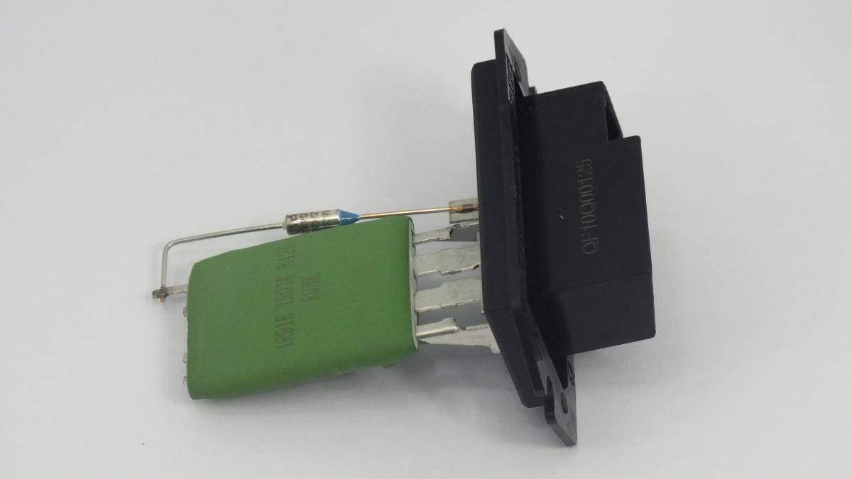
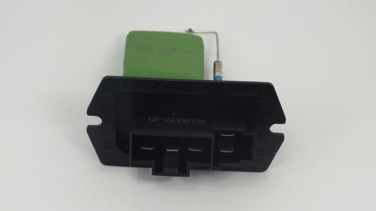
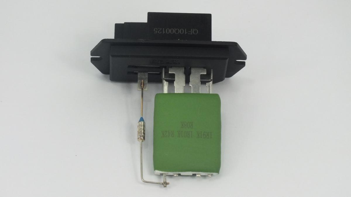
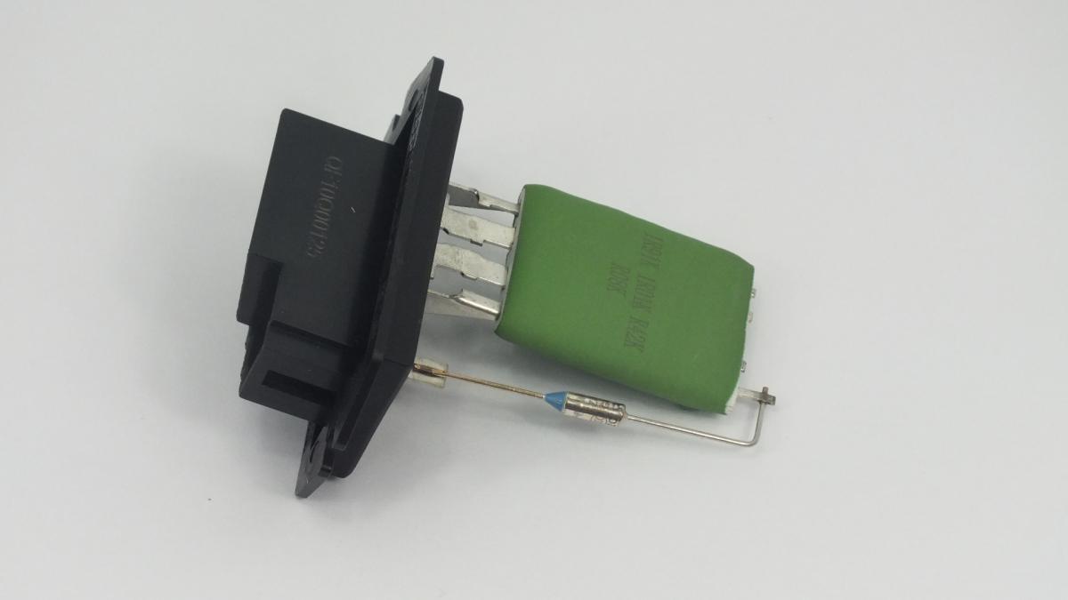
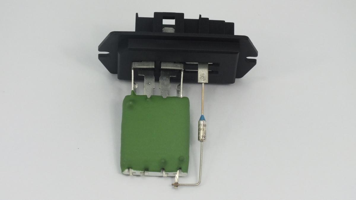
The RESISTOR is a wire-wound or thick-film resistor assembly installed in the blower motor supply circuit — typically mounted in the HVAC housing in the blower airstream or on the firewall adjacent to the blower motor connector — that reduces the voltage supplied to the blower motor by dropping a calibrated portion of the circuit voltage across each resistor stage, providing the discrete low, medium-low, and medium speed settings between the zero-resistance maximum speed position and the switched-off position. The assembly contains two, three, or four individual resistance elements of different values wound from nichrome or stainless steel resistance wire and connected in series with the motor supply line through a switching arrangement controlled by the HVAC speed selector; each speed position connects the motor supply through a different combination of resistor elements to produce a specific voltage at the motor terminals and a corresponding motor speed. The resistor assembly is positioned in the blower airstream specifically to use the airflow generated by the motor at all operating speeds to cool the resistor elements — a resistor operating without adequate airflow across its elements overheats and fails open-circuit within minutes; this is why resistor failure is accelerated on vehicles where the blower is frequently used at low speed in recirculation mode where airflow through the housing is reduced.
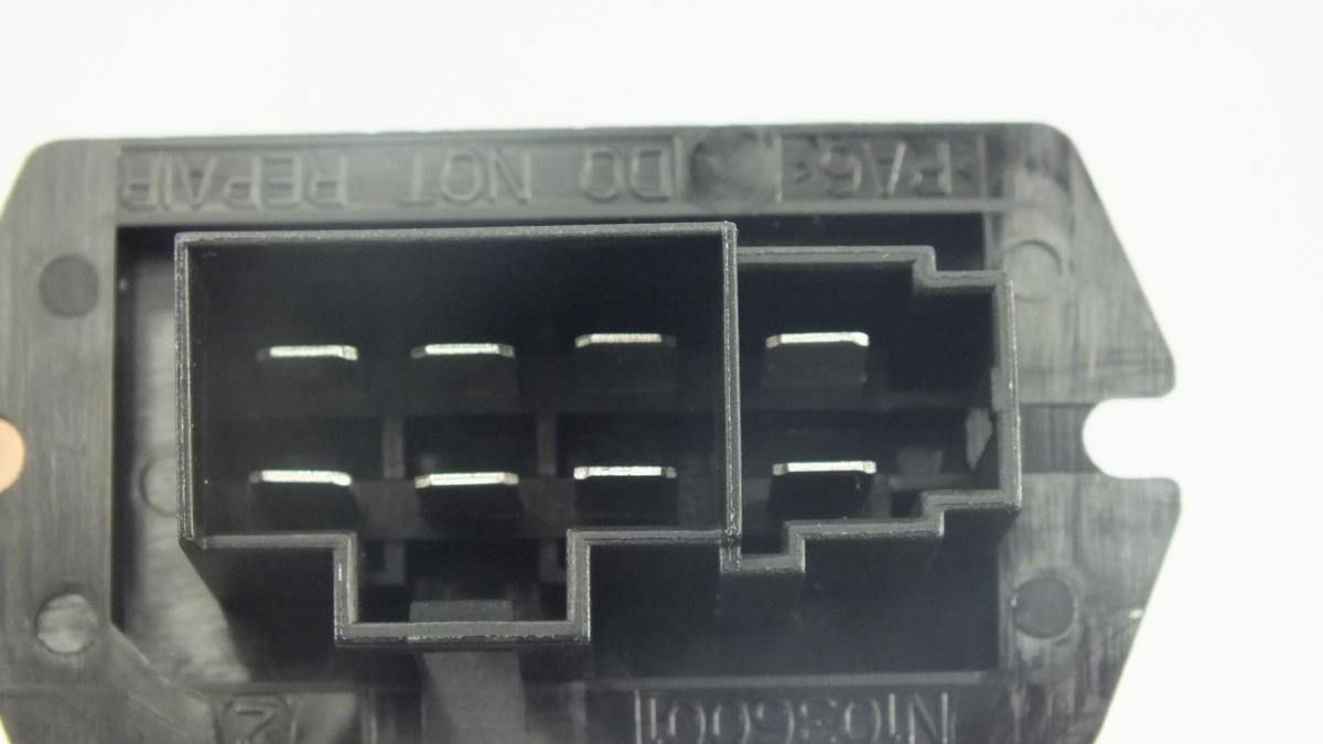
This unit — CHRYSLER 68029175AA — is manufactured to OEM-equivalent specifications: resistance values for each speed stage, rated continuous current capacity, housing dimensions and mounting tab positions for blower housing fitment, electrical connector pinout, and thermal protection characteristics are matched to the original part. Supplied as a direct replacement for standard fitment. Available wholesale from 3.53 USD, MOQ 20 pcs, production lead time 35 days.
Blower resistor packs fail through resistance wire burnout on one or more stages from sustained current overload caused by a partially seized blower motor drawing above its rated current, from thermal fatigue of the wire after high-mileage heat cycling, and from moisture ingress through the blower housing drain that corrodes the resistance wire at a microscopic level before the wire fails open-circuit. The characteristic symptom — blower operating only on maximum speed — results from the high-speed circuit bypassing all resistors through a direct connection, while the failed resistance stages prevent current flow on all lower speed positions. Always test blower motor current draw before replacing the resistor pack; a motor drawing above its rated current will burn out the new resistor at the same rate as the original.
- Measure blower motor current draw before fitting the new resistor pack — connect a clamp ammeter around the motor supply wire and note the current at maximum speed with the ignition on; compare against the motor's rated current specification in the vehicle service data; a motor drawing more than 10% above its rated current will overheat the new resistor at the same rate as the original and must be replaced simultaneously to prevent immediate repeat failure.
- Locate the resistor pack in the blower housing — it is typically mounted on the blower housing wall adjacent to the motor, accessible from under the dashboard on the passenger side or through a dedicated access panel in some vehicle designs; the resistor body protrudes into the airstream through the housing wall and is retained by one or two screws; on some vehicles partial removal of the glovebox is required to access the mounting screws.
- Disconnect the electrical connector before unscrewing the resistor body — the connector locking tab is often stiff from heat cycling; press and hold the release tab fully before pulling the connector straight back to avoid breaking the tab; a broken connector locking tab allows the connector to vibrate loose from the new resistor and produce intermittent blower speed faults that are difficult to diagnose.
- Inspect the blower housing drain outlet at the lowest point of the housing before fitting the new resistor — a blocked drain allows condensate water to pool in the housing below the resistor, splashing onto the hot resistance wire during blower operation and causing corrosion failure; clear any debris from the drain with a thin rod or compressed air; confirm water flows freely through the drain before installing the new unit.
- Verify the new resistor body seats fully against the housing wall with the resistance wire elements projecting into the airstream and no gap between the resistor flange and the housing seating face — a gap allows warm cabin air to short-circuit the airflow over the resistance wire, reducing cooling and causing premature thermal failure; tighten both mounting screws evenly to achieve uniform seating around the full flange perimeter.
- Install the new RESISTOR (CHRYSLER 68029175AA), reconnect the electrical connector until it clicks, test all blower speed settings from minimum to maximum and confirm each setting produces a distinct and correct airflow level, then confirm the maximum speed setting produces the highest airflow before returning the vehicle to service.
| Part | Reason for Combined Replacement |
|---|---|
| Blower Motor OEM ref. varies by vehicle | A blower motor drawing above its rated current from worn brushes, a seized bearing, or degraded winding insulation is the primary cause of premature resistor pack failure — the excess current overheats the resistance wire beyond its thermal design limit. If the resistor pack has burned out rather than failed from simple age, measure motor current draw before fitting a new resistor; a motor drawing above its rated value must be replaced simultaneously to prevent the new resistor from failing at the same rate as the original. |
| Cabin Air Filter OEM ref. varies by vehicle | A blocked cabin air filter forces the blower motor to work against excessive backpressure, increasing current draw above the design rating. The elevated current flows through the resistor pack on all low and medium speed settings, overheating the resistance wire and shortening the resistor's service life. Replacing the cabin filter simultaneously with the resistor pack eliminates this contributing cause and ensures the new resistor operates within its thermal design envelope from the first use. |
| Blower Speed Switch / HVAC Control Unit OEM ref. varies by HVAC system | The blower speed selector switch or HVAC control unit routes current through the resistor pack stages via internal contacts. A switch with worn or burned contacts creates a high-resistance connection in the speed circuit that generates additional heat at the contact point — this intermittent high resistance is often misdiagnosed as a resistor pack fault. If resistor pack replacement does not resolve the speed fault, inspect the speed selector switch contacts before ordering a second resistor. |