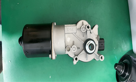
HONDA 76505SWAA02 WIPER, MOTOR
Product Specifications
| HONDA | 76505SWAA02 |
| HONDA | 76505SWAA01 |
| HONDA | 76505TK4A01 |
The WIPER, MOTOR is the windscreen wiper motor and gearbox assembly — an integrated unit combining a permanent-magnet DC electric motor with a worm-and-wheel reduction gearbox that converts the motor's high-speed low-torque rotary output into a low-speed high-torque crank rotation driving the wiper linkage. The motor operates at two speeds — low and high — achieved by switching between a second brush set offset from the main brushes, which effectively changes the motor's back-EMF characteristics and alters its no-load and loaded speeds; a park position switch integrated into the gear wheel stops the motor with the crank at a defined angular position that corresponds to the wiper arms' rest position at the bottom of the windscreen, ensuring the wipers park in the correct position whenever the wiper switch is turned off regardless of where in the sweep cycle the switch is operated. The worm gear reduction ratio — typically 40:1 to 60:1 — provides the mechanical advantage necessary to drive the full wiper linkage through a complete sweep cycle against the combined load of two wiper arm spring contact forces, the aerodynamic drag of the blades at motorway speeds, and the high-friction load of frozen or snow-covered blades in winter conditions. The complete assembly bolts to the wiper linkage frame at a dedicated motor mounting bracket, and the motor's crank output connects to the linkage's drive pin via a press-fit ball-and-socket joint that transmits the motor's rotation into the linkage's reciprocating motion.
This unit — HONDA 76505SWAA02 — is manufactured to OEM-equivalent specifications: motor rated voltage and current at both low and high speed, gear reduction ratio and output torque, crank arm length and drive pin position for the correct sweep arc, park position switch angular setting, mounting bracket bolt pattern, electrical connector pinout for the vehicle's wiper control module, and motor and gearbox housing dimensions for the linkage frame attachment are matched to the original part. Supplied as a complete motor and gearbox assembly with crank arm. Available wholesale from 16.78 USD, MOQ 50 pcs, production lead time 20 days.
Wiper motor and gearbox assemblies fail through armature winding open-circuit or short-circuit from sustained thermal overload — a motor that has been repeatedly stalled against frozen blades or a seized linkage exceeds its thermal protection threshold and burns the armature winding; through brush and commutator wear after high-mileage operation that progressively increases motor resistance and reduces output torque until the motor can no longer sweep the linkage against normal friction loads; through worm gear tooth fracture from attempting to drive frozen or snow-packed blades at high speed when the high torque demand exceeds the gear's load rating; and through park position switch contact wear that causes the wipers to stop in a random position rather than at the designed park location.
- Confirm the wiper linkage pivots rotate freely before installing the new motor — disconnect the motor from the linkage drive pin and manually push and pull the linkage through its full travel range; both pivot posts must rotate smoothly with no binding or roughness; a linkage with seized pivot bearings will stall the new motor within a short period of installation; if the linkage is stiff, identify and address the seized pivot before installing the new motor to protect the motor's winding from overload.
- Connect the motor's crank arm to the linkage drive pin at the correct crank angle before tightening the motor mounting bolts — the crank angle at installation determines the phase relationship between motor rotation and the linkage's sweep position; installing the crank at the wrong angle shifts the park position and the sweep arc relative to their designed positions; the motor crank should be connected to the linkage with the crank at the park position angle — typically marked by a reference line or index mark on the new motor's gearbox housing.
- Place the wipers in their park position before removing the old motor — operate the wipers and switch them off to allow them to park at the screen base; removing the motor from the linkage with the wipers mid-screen leaves the linkage at an unknown crank angle that may not correspond to the new motor's park position reference; if the old motor cannot be parked first, mark the crank arm position on the linkage with a paint pen before removal.
- Torque all motor mounting bolts to the OEM specification — the motor must be securely located on the linkage frame to prevent vibration-induced rattle and to maintain the precise crank-to-linkage geometry through the full sweep cycle; typical motor mounting bolt torque is 8–15 Nm; undertightening allows the motor to vibrate loose and shift the crank alignment over time; do not overtighten into the motor's cast housing bosses.
- On vehicles with rain-sensing or auto-wiper systems, perform the wiper calibration procedure via scan tool after motor replacement — the body control module may store the park position switch timing as an adaptive value; replacing the motor with a unit whose park switch actuates at a slightly different crank angle may cause the wipers to park fractionally above the designed screen base position; clearing the adaptive value and performing the recalibration procedure via the scan tool's wiper calibration function restores the correct park position reference for the new motor.
- Install the new WIPER, MOTOR (HONDA 76505SWAA02), reconnect the wiper linkage and electrical connector, operate the wipers at both low and high speed confirming correct sweep arc and blade synchronisation, switch the wipers off from mid-sweep confirming the blades park at the screen base in the designed position, and road test at motorway speed confirming the blades do not lift from the screen before returning the vehicle to service.
| Part | Reason for Combined Replacement |
|---|---|
| Wiper Linkage Assembly Complete linkage without motor — OEM ref. varies | A motor that failed from thermal overload from a seized linkage must be paired with a replacement linkage — the seized pivot that destroyed the original motor will destroy the new motor at the same rate if left in place. Additionally, a linkage that has been operated against an overloading motor has been subjected to abnormal torque impulses at the ball-and-socket drive pin connection; inspect the drive pin socket in the linkage for wear or cracking from these overloads before connecting the new motor. |
| Wiper Blades Driver and passenger — OEM length per vehicle | Wiper motor replacement provides the opportunity to fit new blades simultaneously. A motor that has been struggling to complete its sweep cycle against high blade friction — from hardened rubber or incorrect contact force — has been operating above its rated torque for an extended period before complete failure. Fitting new blades with the new motor ensures the motor starts its service life against the designed blade resistance rather than against the elevated friction that contributed to the original motor's overload failure. |
| Wiper Relay OEM ref. varies by body electrical system | On vehicles where the wiper motor is controlled through a dedicated relay rather than directly by the body control module, the relay contacts accumulate arcing damage each time the motor is switched on and off under load. A relay that has been switching a motor with failing armature resistance — requiring higher current to maintain speed — has been arcing at above its rated current on every switch cycle. If the motor failed from armature overload, inspect the relay's switching contacts for burn damage and replace the relay simultaneously with the motor to prevent the arcing-damaged relay from failing in the closed position and causing the new motor to run continuously. |