CHRYSLER 05161435AA CUSHION CTR SUPPORT

Product Specifications
| CHRYSLER | 05161435AA |
| CHRYSLER | 05127290AA |
| CHRYSLER | 05142476AA |
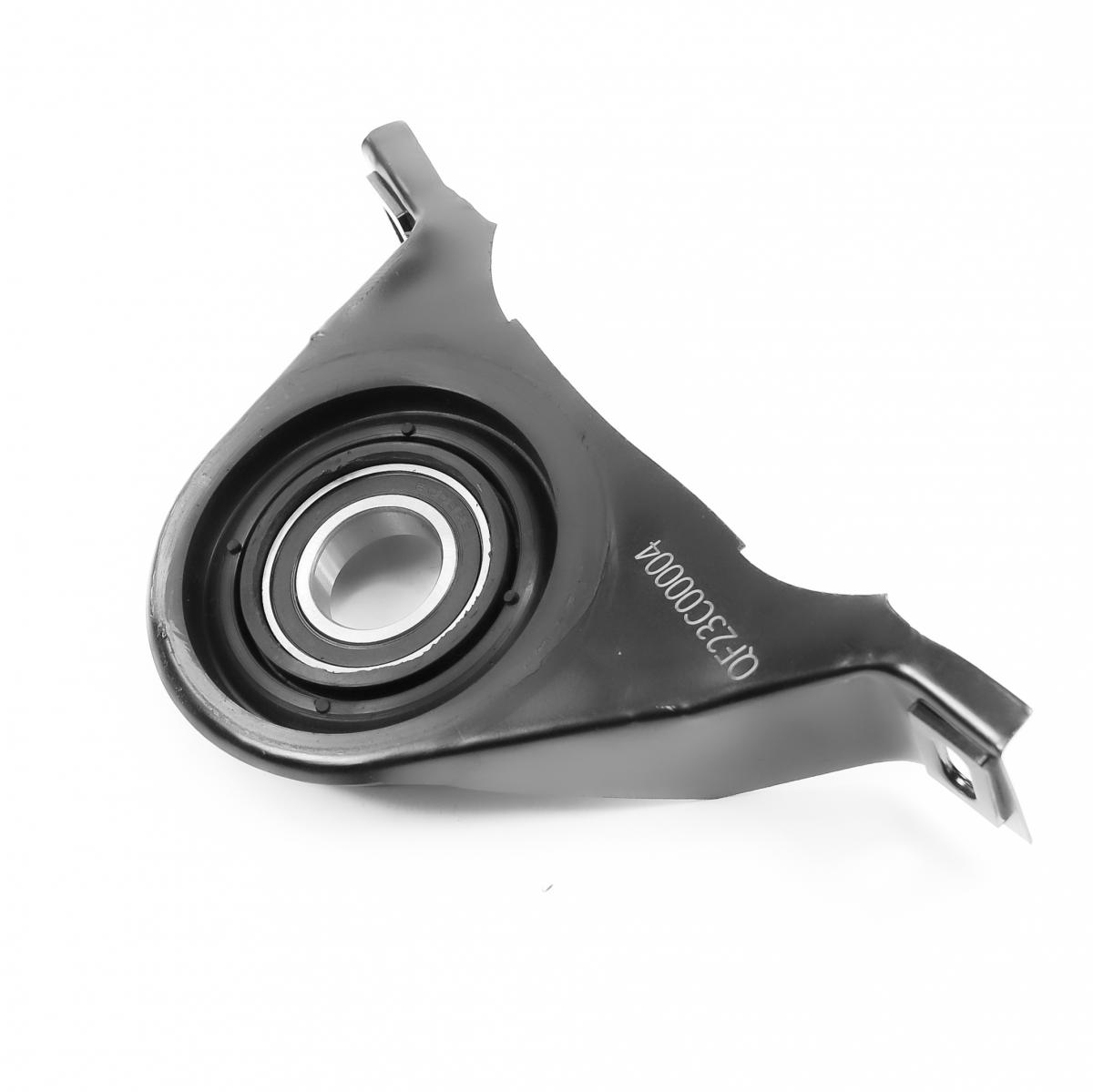
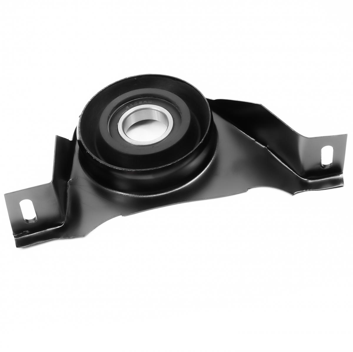
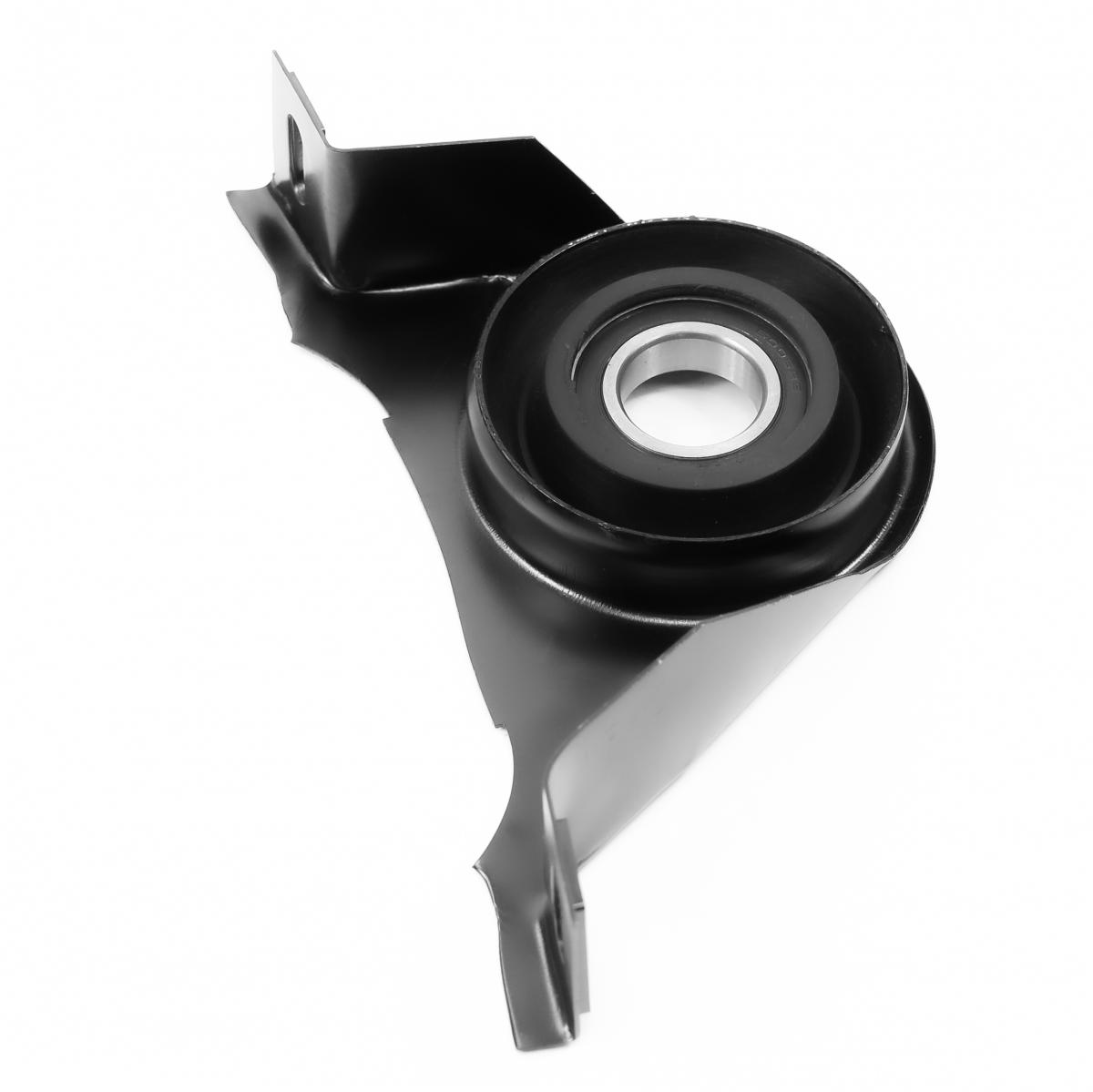
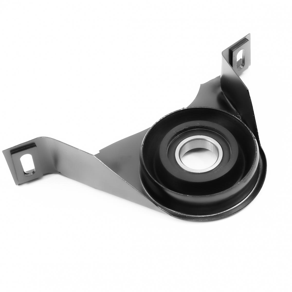
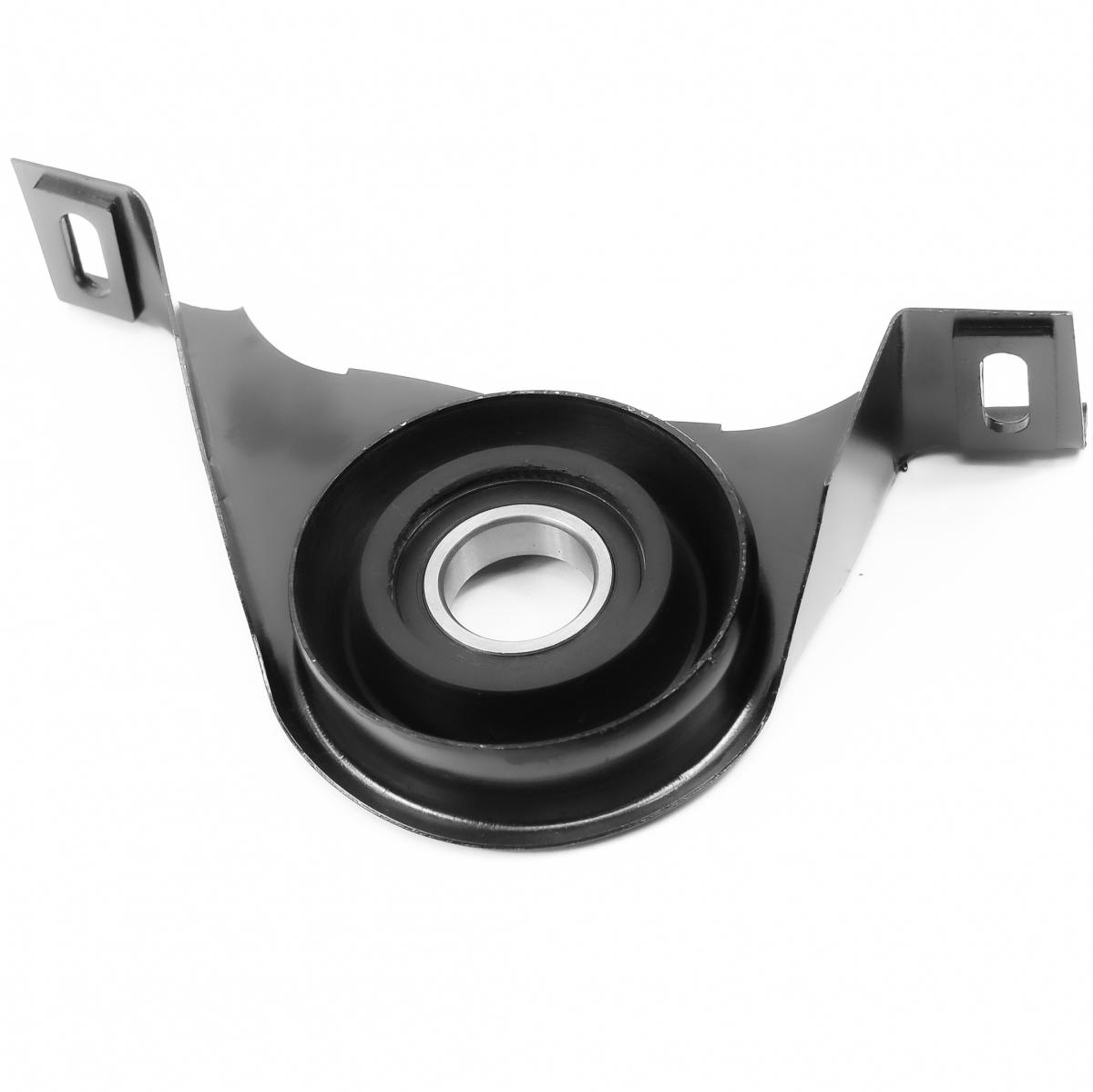
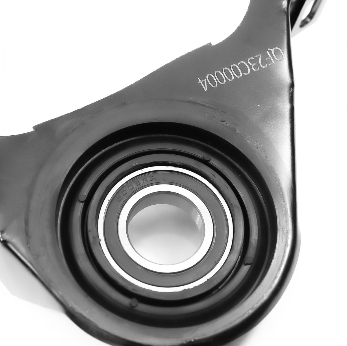
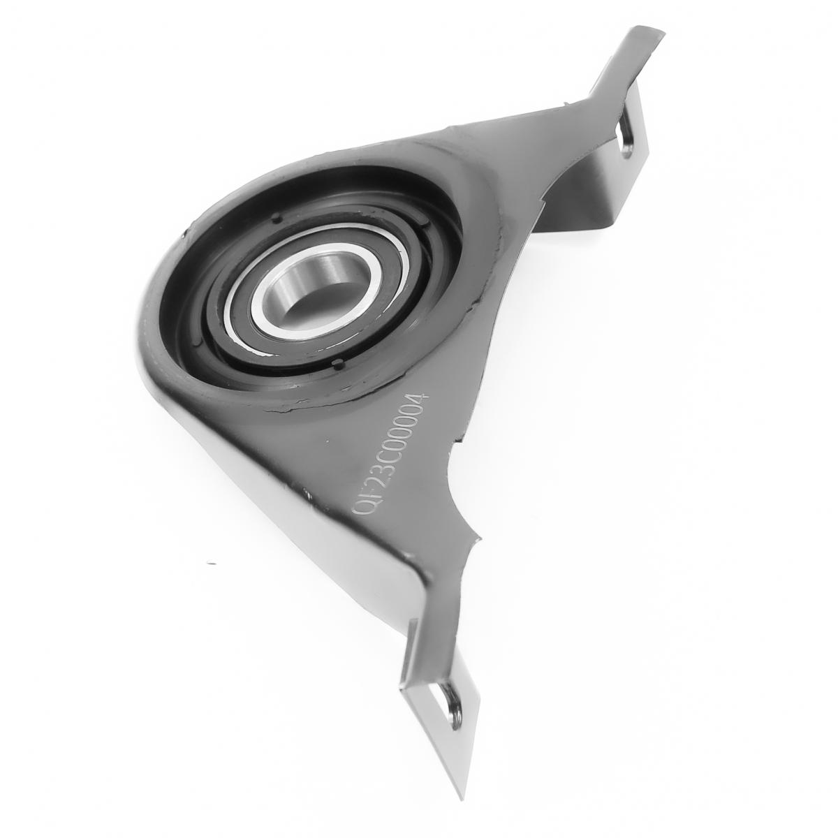
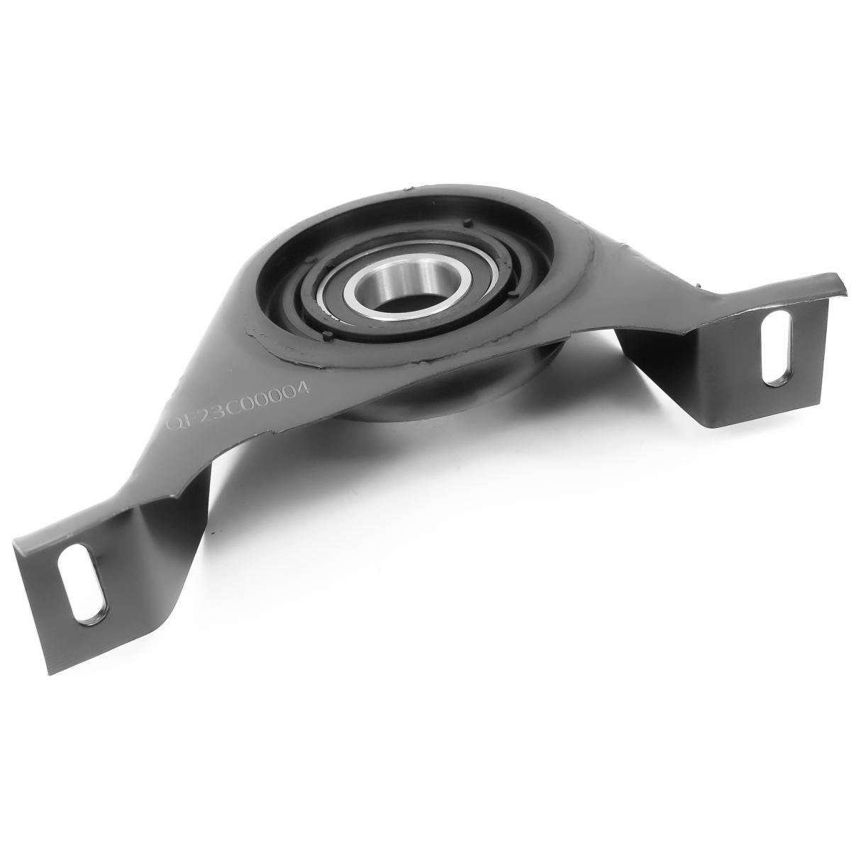
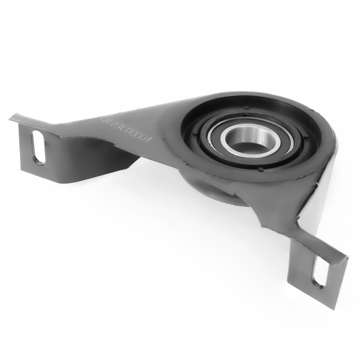
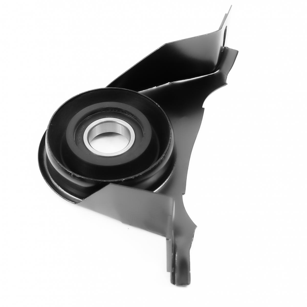
The CUSHION CTR SUPPORT is the propeller shaft centre bearing support — also called the centre bearing hanger or intermediate shaft bearing — that supports the midpoint of a two-piece propeller shaft on rear-wheel-drive and four-wheel-drive vehicles, preventing the shaft from sagging under its own weight and from oscillating at its natural resonant frequency during operation. The assembly integrates a sealed deep-groove ball bearing pressed into a rubber-bonded elastomeric isolation ring — the rubber cushion — which is in turn encased in a stamped steel bracket that bolts to the vehicle's body floor tunnel, chassis crossmember, or transmission mount crossrail at a precisely defined height that positions the propeller shaft sections at the designed driveline angle. The ball bearing supports the propeller shaft's rotational movement while carrying the static and dynamic radial loads from the shaft's weight and from any residual imbalance; the elastomeric rubber ring isolates the bearing and shaft vibration from the vehicle body, attenuating the rotational-frequency vibration that would otherwise transmit as a droning or humming noise through the floor into the cabin. The rubber isolation element's stiffness is calibrated to provide adequate shaft support while maintaining sufficient compliance to absorb the axial and radial movement of the driveshaft segments that occurs during suspension travel and body flex — a rubber element that is too stiff transmits all shaft vibration to the body; one that is too soft allows the shaft to oscillate and may allow the shaft sections to contact the body tunnel.
This unit — CHRYSLER 05161435AA — is manufactured to OEM-equivalent specifications: ball bearing bore diameter and outer diameter for propeller shaft stub fitment, bearing dynamic load rating, rubber cushion Shore hardness and isolation compliance, bracket outer dimensions and mounting hole positions for body or chassis attachment, and overall assembly height for the correct driveline geometry are matched to the original part. Supplied as a complete assembly — bearing, rubber cushion, and bracket — ready for installation. Available wholesale from 5.83 USD, MOQ 50 pcs, production lead time 61 days.
Centre support bearings fail through rubber cushion cracking and delamination from ozone and age that destroys the isolation function and allows the bearing housing to contact the steel bracket directly, transmitting all shaft vibration to the body as a pronounced droning noise; through ball bearing fatigue from sustained operation at high shaft speeds with the rubber already degraded, which subjects the bearing to amplified vibration loads it was not designed to absorb alone; and through water ingress into the bearing through a degraded seal that corrodes the raceways and produces a characteristic growling noise at shaft rotational frequency.
- Mark the orientation of the propeller shaft sections relative to each other before separation — two-piece propeller shafts are factory-balanced as a complete assembly; the shaft sections must be reinstalled in the same relative angular orientation to preserve the balance; use a paint pen to mark the mating flange positions on both sections at the centre joint before splitting the shaft; failure to maintain the original phasing requires a full driveshaft rebalance on a balancing machine after installation.
- Support both propeller shaft sections independently before unbolting the centre support bracket — the two shaft sections are heavy and will drop suddenly when the centre support is released if unsupported; use a transmission jack under each section or tie them up with safety straps before removing any bracket bolts; an unsupported shaft section that drops can damage the universal joint at each end by over-extending the joint cup beyond its travel limit.
- Press the old bearing off the shaft stub and the new bearing onto the shaft using the correct diameter driver cups — never drive a centre bearing on or off with a hammer striking the outer race; apply installation force only to the inner race using a driver cup matched to the inner race diameter; applying force to the outer race during installation Brinell-dents the raceways before the bearing enters service; use a bearing press or a drawbolt tool that applies steady axial force through the correct cup.
- Install the new centre support bracket at the correct mounting height — the bracket height determines the propeller shaft's operating angle at both adjacent universal joints; a bracket mounted too high or too low changes both joints' operating angles simultaneously; confirm the bracket height matches the OEM specification — typically verified by comparing with the old bracket's mounting shim stack or by confirming the shaft is centred in the body tunnel without sagging or fouling the tunnel at any suspension position.
- Torque all bracket mounting bolts to OEM specification with the rubber cushion in its unloaded position — the bracket should be tightened with the shaft at its normal laden ride height so the rubber cushion is at its design pre-stress position; tightening with the shaft hanging at full droop twists the rubber into a pre-stressed position that cracks it prematurely; if exact ride height cannot be replicated, tighten the bolts hand-tight and lower the vehicle to ride height before final torquing.
- Install the new CUSHION CTR SUPPORT (CHRYSLER 05161435AA), reassemble the shaft sections in the marked orientation, torque all flange bolts to OEM specification, lower the vehicle, and road test at progressive speeds from 40 to 130 km/h confirming the drivetrain droning and vibration have been eliminated at all speeds; perform a check from the passenger cabin at 100 km/h specifically listening for any residual vibration frequency that may indicate a companion universal joint requiring attention.
| Part | Reason for Combined Replacement |
|---|---|
| Universal Joint Set Front, centre, and rear UJs — application-specific | A failed centre bearing that has allowed the propeller shaft to oscillate at amplitudes beyond the designed travel of the adjacent universal joint cups subjects those joints to accelerated needle bearing wear. With the propeller shaft removed for centre bearing access, rotate each UJ through its full angular range and feel for roughness, binding, or axial play in the cups — any roughness confirms bearing needle wear that will produce vibration within a short mileage of the centre bearing repair. Replacing worn UJs simultaneously eliminates a repeat shaft removal within a short interval. |
| Propeller Shaft Flange Seal Differential or gearbox output seal — application-specific | The propeller shaft flanges at both the gearbox output and the differential input are disconnected during centre bearing replacement, exposing the shaft oil seals at these interfaces. A seal that has been running in contact with a vibrating propeller shaft from a failed centre bearing will have accumulated accelerated lip wear from the shaft's eccentric runout. Inspect both flange seals for weeping and replace simultaneously if any sign of oil migration is found — refitting a leaking seal to a newly stabilised shaft produces an oil contamination of the UJ needle bearings within a short period. |
| Gearbox and Differential Oil GL-4 or GL-5 per OEM specification | With the propeller shaft flanges disconnected, this is the correct time to check the gearbox and differential oil levels and condition simultaneously. Oil that has been in service for an extended period in both units should be renewed — the same vibration that destroyed the centre bearing may have subjected the UJs and differential to abnormal loads that have generated metallic particles in the differential oil; inspect both drain plugs for metallic accumulation and renew the oil if particles are found. |