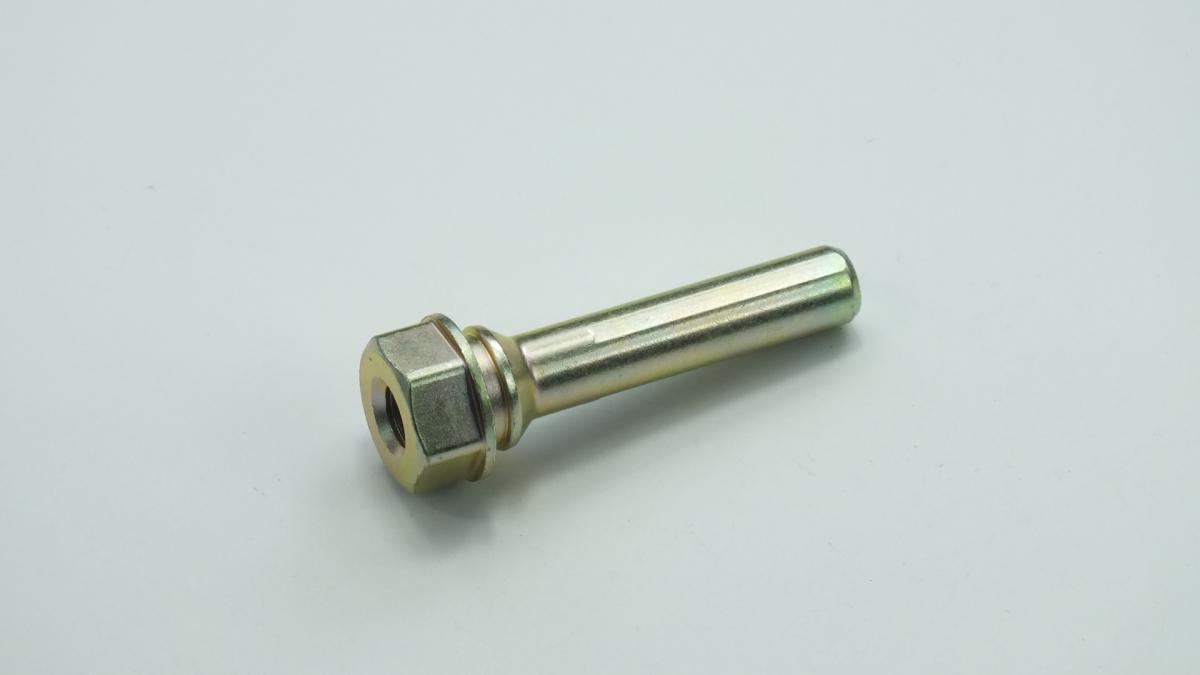
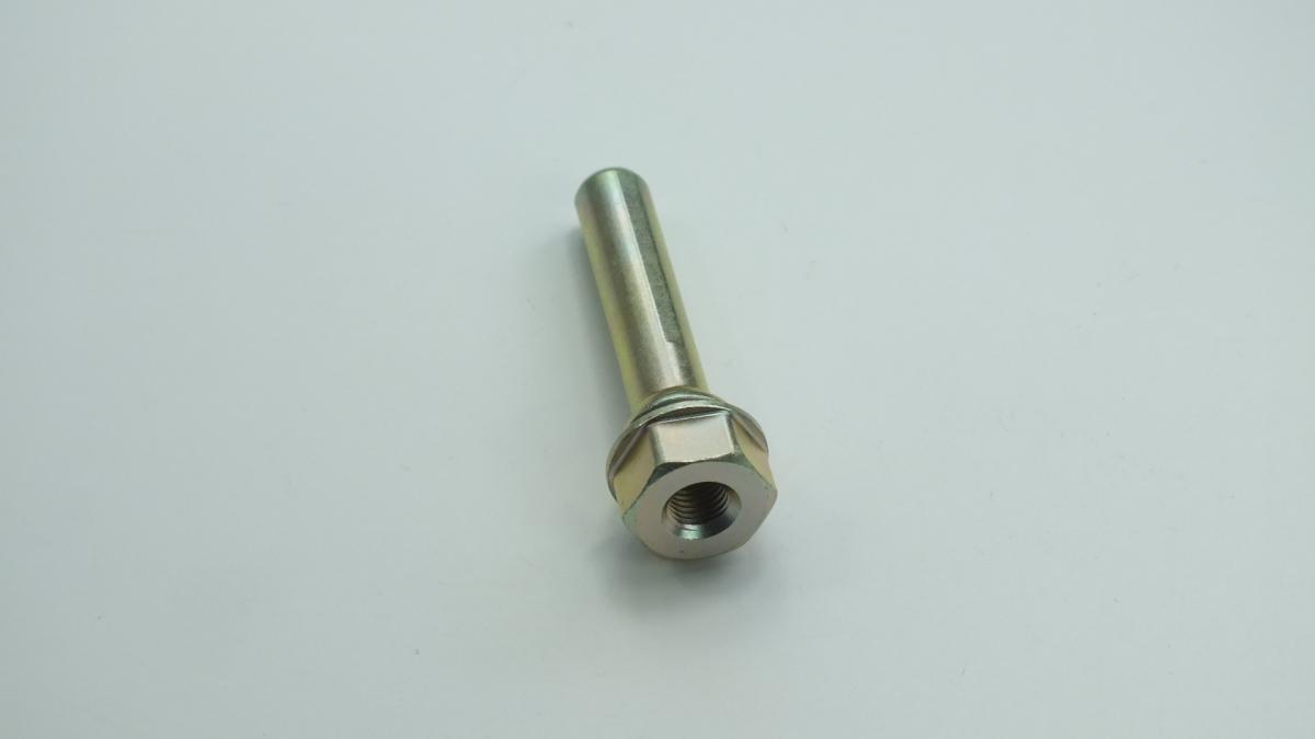
HYUNDAI/KIA 582211H000 PIN
Product Specifications
| HYUNDAI/KIA | 582211H000 |
| HYUNDAI/KIA | 582211G300 |
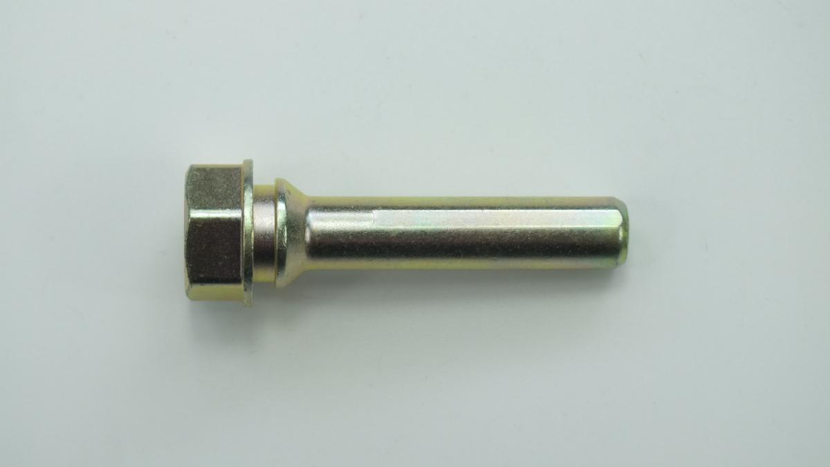
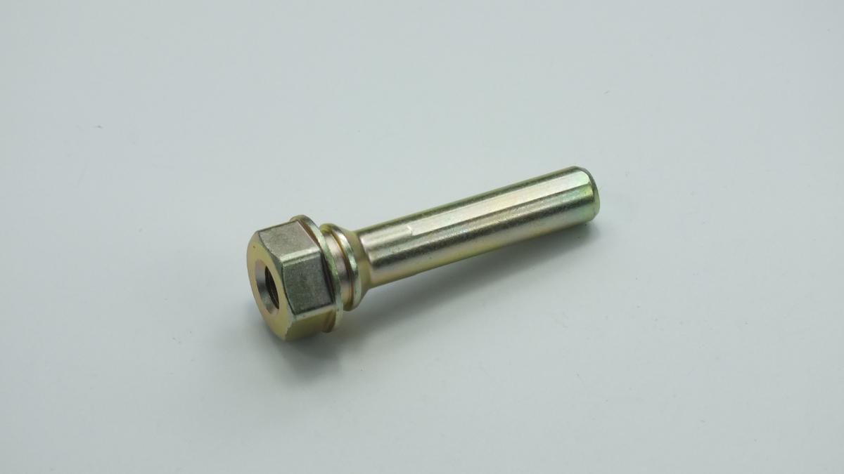
The PIN is a hardened and precision-ground steel slide pin — also called a caliper guide pin or caliper bolt — that enables the floating disc brake caliper body to slide freely in the lateral direction along the axis of the wheel as the brake pads wear, ensuring that both the piston-side inner pad and the reaction-side outer pad maintain equal and uniform contact pressure against both faces of the brake disc throughout the pad's service life. On a floating single-piston caliper design, only the inner brake pad is pushed directly against the disc by the hydraulic piston; the outer pad is pressed against the disc by the equal and opposite reaction force that the caliper body experiences when the piston pushes — but this reaction force can only be applied to the outer pad if the caliper body is free to slide axially along the guide pins toward the disc. The guide pin threads into the anchor bracket that is bolted to the steering knuckle and carries the caliper body on its precision-ground shank — the caliper body's bore slides over the shank on a thin film of caliper slide pin lubricant retained within a rubber dust boot that seals the pin shank from road contamination; a second guide pin on the opposite end of the caliper provides parallel guidance and prevents the caliper from rocking on a single pin. The precision clearance between the pin shank diameter and the caliper bore diameter — typically 0.01–0.05 mm — determines the caliper's ability to float freely; any corrosion or contamination that occupies this clearance zone prevents free sliding and causes unequal pad wear, brake drag, and the steering pull that results from asymmetric braking force between left and right calipers on the same axle.
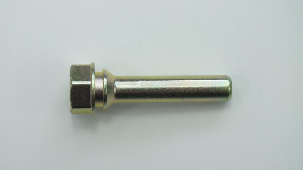
This unit — HYUNDAI/KIA 582211H000 — is manufactured to OEM-equivalent specifications: shank diameter and surface finish, threaded engagement length and thread form for the anchor bracket, shank length for the correct caliper bore engagement depth, dust boot groove geometry for the rubber boot retention, and material and heat treatment for the designed hardness and corrosion resistance are matched to the original part. Supplied individually or in a two-pin kit with new dust boots and lubricant. Available wholesale from 0.45 USD, MOQ 200 pcs, production lead time 64 days.
Caliper guide pins fail through corrosion of the precision-ground shank surface when the dust boot tears or becomes dislodged — road salt and water entering through the damaged boot deposits a corrosion layer on the shank that occupies the clearance zone and prevents the caliper from sliding; the resulting brake drag and uneven pad wear are progressive faults that become a roadworthiness defect and accelerate disc and pad wear simultaneously. A seized guide pin is one of the most common causes of a caliper that drags, a car that pulls to one side under braking, and a brake pad that wears rapidly on one side only — symptoms that are frequently misattributed to a failed caliper piston before the guide pins are inspected.
- Clean the anchor bracket guide pin bores thoroughly before installing new pins — remove all corrosion deposits, old lubricant residue, and debris from inside both bores using a wire brush or a dedicated caliper bore cleaning brush; the bore surface must be clean bare metal with no residual corrosion that would restrict pin movement; finish with brake cleaner on a lint-free cloth to remove all cleaning residue; a bore with residual corrosion contamination will seize the new pin within a short operating period despite fresh lubrication.
- Inspect the anchor bracket pin bores for corrosion damage and out-of-round wear before fitting new pins — insert the new pin shank by hand and confirm it moves freely through the full bore length without binding at any position; a bore with corrosion pitting or oval wear from a previously seized pin will not provide the required clearance for free pin movement; if the bore cannot be cleaned to a smooth surface, replace the anchor bracket before fitting new pins.
- Apply only the correct caliper slide pin lubricant to the pin shank — use only a dedicated high-temperature, water-resistant, copper-free caliper guide pin grease — typically silicone or synthetic lithium-based; never use copper grease, standard bearing grease, or petroleum-based lubricants on caliper guide pins; copper grease at the caliper-to-disc interface is a known brake judder cause if it migrates onto the disc face; standard grease washes out in wet conditions and provides no protection; apply a thin even film to the full pin shank length — not to the threads.
- Install the new dust boots before threading the pins into the bracket — slide the boot over the pin shank and seat the inner lip in the pin's boot retaining groove before the pin is threaded into the bracket; attempting to fit the boot after the pin is installed forces the boot over the thread end and risks tearing the boot inner lip; confirm the outer boot lip is correctly seated in the caliper body's boot retaining groove after the pin is fully installed.
- Torque the guide pins to the OEM specification — caliper guide pin torque is typically 25–35 Nm for the large pin and 15–25 Nm for the small pin on most passenger car applications; undertightening allows the pin to back out of the bracket under brake vibration, causing caliper misalignment; overtightening strips the bracket thread; always use a torque wrench — never tighten by feel on a safety-critical brake component.
- Install the new PIN (HYUNDAI/KIA 582211H000) on both pins simultaneously — always replace both guide pins on the same caliper as a set — refit the caliper with new brake pads, lower the vehicle, pump the brake pedal to seat the pads against the disc, and perform a road test confirming no brake drag, no pulling, and even braking feel before returning the vehicle to service.
| Part | Reason for Combined Replacement |
|---|---|
| Brake Pads Axle set — OEM ref. varies by caliper application | A caliper with seized guide pins will have produced severely uneven pad wear — one pad worn through while the opposite pad retains most of its friction material. The worn pad must be replaced; the partially worn pad cannot be reused against a new pad of full thickness because the thickness difference prevents both pads from making uniform contact with the disc simultaneously. Always replace brake pads as an axle set simultaneously with the guide pins, and inspect the disc for scoring from the worn-through pad. |
| Brake Disc OEM ref. varies by axle position | A caliper drag from seized guide pins subjects the brake disc to continuous partial engagement that generates abnormal heat and uneven thermal loading — the disc develops hard spots, surface hardening, and thickness variation from sustained drag contact. Measure the disc for runout and minimum thickness after guide pin replacement and replace the disc if any measurement is outside the OEM tolerance — a disc with thickness variation from drag wear will cause judder on the first brake application with new pads. |
| Caliper Dust Boot Set Two boots per caliper — guide pin application-specific | The dust boots are the primary protection for the guide pin shanks against road contamination — a torn or dislodged boot is always the root cause of guide pin corrosion seizure. New dust boots must always be fitted simultaneously with new guide pins; fitting new pins into old or damaged boots immediately begins exposing the new shank to the same contamination path that seized the original pin. Always include new boots in the guide pin replacement parts order. |