HONDA 33146SEAG01 SENSOR SUB-ASSY

Product Specifications

Product quality
OEM Equivalent Grade
starstarstar
300 sold
Wholesale price USD $6.19
Wholesale price CNY ¥42
bolt MOQ (Minimal order)
10 pcs
local_shipping Production time
25 days
package_2 Shipping Weight: 0.072 kg
HONDA 33146SEAG01
HONDA 06136SWAR01
HONDA 33136SEAG01
Overview & Operating Principle

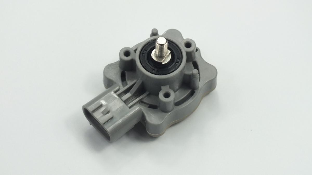
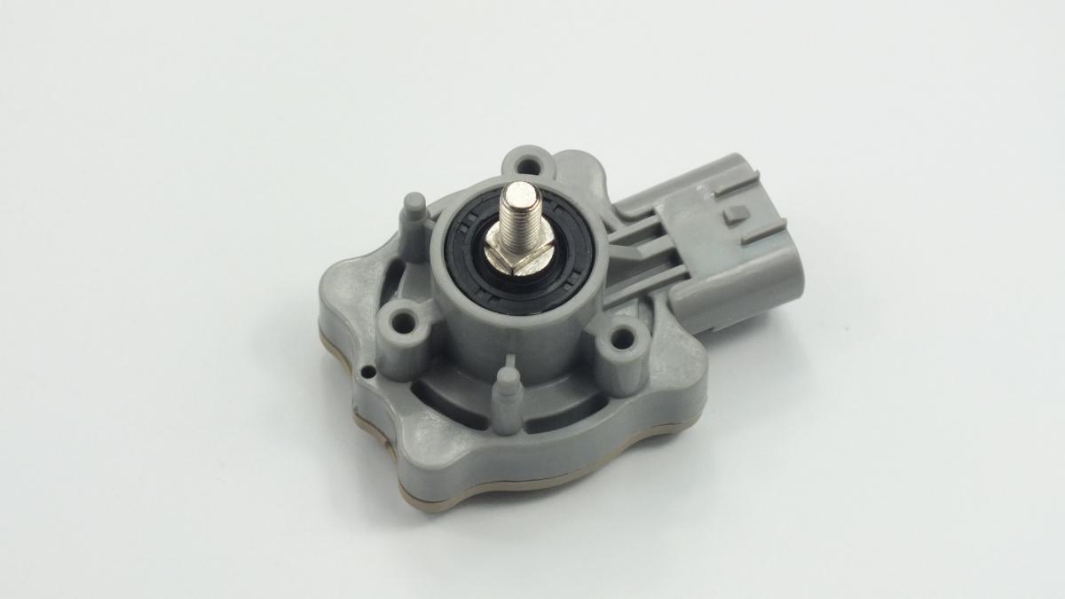
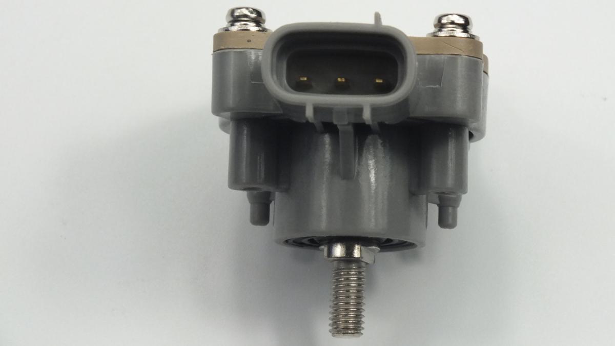
The SENSOR SUB-ASSY is a rotary or linear position sensor mounted between the vehicle body structure and the suspension control arm or axle beam that continuously measures the vertical distance between the body and the wheel centre — the ride height — at each monitored corner, converting this mechanical displacement into an analogue voltage or digital PWM signal that the suspension or lighting control module processes to manage dynamic vehicle systems. On vehicles with electronically controlled air suspension or adaptive damper systems, the sensor provides the closed-loop feedback signal that the suspension control module uses to command the compressor, valve block, or damper actuator to maintain the target ride height regardless of passenger load, luggage weight, or dynamic body attitude during cornering and braking. On vehicles with static coil spring suspension the same sensor type serves the automatic headlamp levelling system, adjusting the headlamp beam angle in real time to compensate for load-induced nose-up pitch that would otherwise dazzle oncoming drivers. The sensor mechanism is either a Hall-effect rotary sensor whose output voltage varies with the angle of a lever arm connected to the suspension via a linkage rod, or a linear potentiometer whose wiper position tracks suspension travel directly.

This unit — HONDA 33146SEAG01 — is manufactured to OEM-equivalent specifications: sensor travel range and output voltage curve, lever arm geometry and mounting boss positions, linkage rod ball joint diameter and length, operating temperature range, connector pinout, and body mounting bracket geometry are matched to the original part. Supplied as a direct plug-and-play replacement for standard fitment. Available wholesale from 6.19 USD, MOQ 10 pcs, production lead time 25 days.

Ride height sensors fail through potentiometer track wear producing dead spots in the output signal, linkage rod ball joint wear allowing play that introduces position error into the suspension module's calculations, connector corrosion from underbody moisture and road salt, and lever arm fracture from road debris impact or suspension over-travel. A failed or inaccurate ride height sensor on an air suspension vehicle causes the compressor to run continuously trying to reach an unachievable height target, rapidly overheating the compressor motor — a sensor fault that is not diagnosed and corrected promptly converts a low-cost sensor replacement into a combined sensor and compressor replacement.

Symptoms & Diagnostics
Air suspension warning light with fault codes indicating a specific corner is out of ride height range or sensor signal is invalid — the suspension control module is receiving a signal from the affected corner that is outside its expected range for any physically achievable suspension position; confirm supply voltage and ground at the sensor connector before replacing the sensor body.
Vehicle sitting permanently at one extreme of its ride height range — low to the ground or raised to maximum height — at one or more corners — the sensor output is fixed at its minimum or maximum voltage, indicating either a failed potentiometer track, a seized linkage ball joint holding the lever at end of travel, or a disconnected linkage rod allowing the lever to fall to its stop position.
Air suspension compressor running continuously or cycling at abnormally short intervals — an erratic or drifted sensor signal is causing the suspension module to continuously hunt for a target ride height that the sensor never confirms has been reached; monitor the sensor live voltage on a scan tool while gently moving the suspension through its travel range to identify dead spots or non-linear output.
Headlamp beam aimed too high or too low with no change in vehicle load — the ride height sensor serving the automatic headlamp levelling system has drifted or failed, causing the levelling actuator to hold the lamp at an incorrect angle; on vehicles without air suspension this is the primary symptom of sensor failure.
Ride height correct at one end of suspension travel but incorrect at the other — the sensor potentiometer has developed a dead spot or resistive track wear in a specific angular range; the suspension module correctly manages height at positions where the track is serviceable but loses control when suspension moves through the worn section.
Intermittent suspension fault codes that clear themselves after the vehicle is driven — connector pin corrosion producing a high-resistance connection that generates signal noise at the sensor output; the fault clears as thermal expansion improves pin contact temporarily; inspect and clean the sensor connector with electrical contact cleaner before replacing the sensor body.
Logistics & Customs
International HS Code
9031.80
EAEU Customs Code (TN VED)
9031 80 380 0
Typical Net Weight
0.072 kg
Country of Manufacture
China
Standard MOQ
10 pcs
Production Lead Time
25 days
Always verify the exact 8-digit or 10-digit subheading with your customs broker for the destination country, as tariff schedules and duty rates vary by jurisdiction.
Installation Tips
  1. Use a scan tool to command the suspension to standard ride height and record the sensor live voltage before disconnecting anything — confirming the faulty sensor's output at known ride height provides a baseline for verifying the new sensor's output after installation; it also confirms whether the fault is a fixed offset (drifted calibration) or a total signal loss (wiring or potentiometer failure).
  2. Disconnect the linkage rod from the suspension control arm ball pin before unbolting the sensor body from its bracket — releasing the linkage first allows the sensor lever to move to its free position without the linkage rod constraining it; attempting to unbolt the sensor body while the linkage is still attached under tension can snap the lever arm or strip the sensor mounting threads.
  3. Note the sensor lever arm angle relative to the sensor body at standard ride height by marking both with a paint pen before removal — the new sensor must be installed with the lever in the same angular position at standard ride height to ensure the suspension module's calibration reference point falls within the sensor's linear output range; a sensor installed with the lever at the wrong angle will require a full calibration procedure even if the sensor itself is functioning correctly.
  4. Inspect the linkage rod ball joints at both ends before refitting — press the ball joint studs laterally and axially to check for play; a linkage rod with worn ball joints introduces mechanical hysteresis into the height measurement that the suspension module cannot distinguish from an actual height change, causing the compressor or damper to hunt continuously even with a new sensor installed.
  5. Route the sensor wiring harness clear of moving suspension components and secure it in all original clip positions — the harness must have sufficient slack to accommodate full suspension travel in both compression and rebound without tension; a harness pulled taut at full rebound will fracture the sensor connector pins within a short period of road use.
  6. Install the new SENSOR SUB-ASSY (HONDA 33146SEAG01), reconnect the linkage rod and wiring connector, lower the vehicle to a level surface at standard ride height, perform the suspension height calibration or sensor relearn procedure via scan tool as required by the OEM procedure for this vehicle, verify the sensor live voltage matches the expected value at standard ride height, clear all stored fault codes, and confirm the suspension system holds the correct height under static load before returning the vehicle to service.
Tools: OBD-II scanner with suspension module live data and calibration function, paint pen for lever angle reference, multimeter for supply voltage verification, electrical contact cleaner for connector inspection.
Frequently Asked Questions
Is a calibration or relearn procedure always required after replacing a ride height sensor?
Yes, on all vehicles with electronically controlled suspension a height sensor calibration is required after replacement. The suspension control module stores a reference voltage for each sensor that corresponds to the standard ride height position — this reference is specific to the installed sensor's output characteristics and must be reset to the new sensor's output. Without calibration the module commands an incorrect target height and the suspension will not level correctly under load. The procedure is performed on a level surface with the vehicle unloaded via the manufacturer's scan tool software. On vehicles with only headlamp levelling (no air suspension), the levelling system performs a self-calibration on the first ignition cycle after the fault code is cleared. ok.parts supplies ride height sensors at wholesale MOQ from 6.19 USD per unit.
Should all ride height sensors be replaced simultaneously or only the faulty one?
Replace only the sensor confirmed as faulty by fault code and live data diagnosis — ride height sensors do not have a fixed service life and the remaining sensors may have many years of serviceable life remaining. However, if the vehicle has all-round air suspension and the failed sensor has drifted due to potentiometer wear rather than a specific damage event, inspect the remaining sensors' live output curves on a scan tool for dead spots or non-linearity — sensors of the same age on the same vehicle may be at a similar wear stage. If multiple sensors show degraded output, replacing all simultaneously avoids repeat calibration and labour costs within a short interval.
How does the OEM-equivalent aftermarket unit compare to the genuine OEM part?
OEM-equivalent units in this catalogue replicate the current OEM design geometry and material specification. Quality is verified against OEM cross-reference data. When ordering in bulk, confirm with our team that the specification matches the latest OEM revision for your application.
Is white-label or custom packaging available for wholesale orders?
Yes. ok.parts works directly with the manufacturing facility and can accommodate neutral white-label packaging or fully branded packaging with your company logo, part numbers, and barcode. Minimum order quantities and lead times for custom packaging may differ from standard stock. Contact the team via the inquiry form to discuss your specific requirements.
Frequently Replaced Together