CHRYSLER 5033313AA SENSOR WATER TEMPERATURE
Product Specifications
| CHRYSLER | 5033313AA |
| CHRYSLER | 05033313AA |
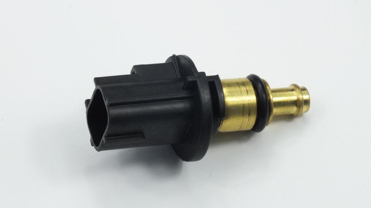
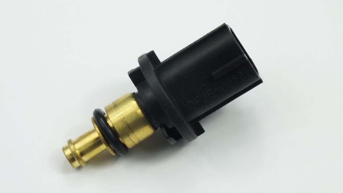
The SENSOR WATER TEMPERATURE is a negative temperature coefficient (NTC) thermistor sensor threaded into the engine coolant circuit — typically in the thermostat housing, cylinder head water jacket, or coolant outlet pipe — whose electrical resistance decreases predictably and non-linearly as coolant temperature increases, providing the ECU and instrument cluster with a continuous analogue voltage signal that represents the engine's thermal state for fuel injection management, ignition timing, fan control, thermostat monitor function, and temperature gauge display. The sensor consists of a sintered metal oxide thermistor bead with a precisely characterised resistance-temperature curve — typically 2,000–3,000 ohms at 20°C cooling down to 150–300 ohms at 80°C operating temperature — encapsulated in a brass or stainless steel housing with a machined thread for coolant circuit installation and sealed against coolant ingress by the thread engagement and a copper or aluminium sealing washer. The ECU supplies a fixed reference voltage — typically 5V — through an internal pull-up resistor to the sensor signal wire; as the sensor resistance decreases with temperature, more current flows and the voltage measured at the ECU input falls proportionally, providing the temperature-to-voltage conversion the ECU uses for all coolant-temperature-dependent functions.
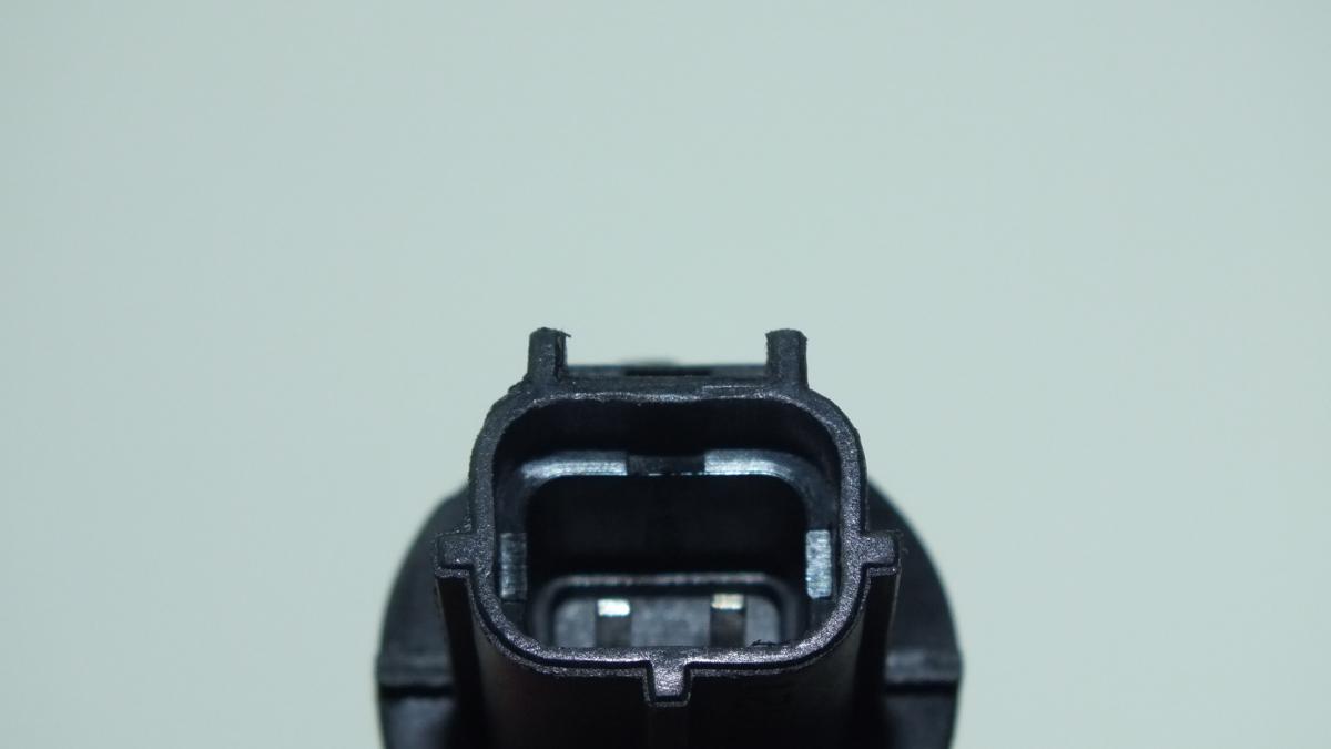
This unit — CHRYSLER 5033313AA — is manufactured to OEM-equivalent specifications: NTC resistance-temperature curve and calibration tolerance, housing thread size and pitch, overall insertion depth, sealing washer type, operating pressure rating, and connector pinout are matched to the original part. Supplied as a direct replacement for standard fitment. Available wholesale from 0.98 USD, MOQ 200 pcs, production lead time 45 days.
Coolant temperature sensors fail through thermistor element drift from prolonged operation in degraded acidic coolant that attacks the bead's sintered oxide surface, producing a resistance offset that causes the ECU to receive an incorrect temperature — either systematically high or low relative to actual coolant temperature; through connector pin corrosion from underbonnet moisture producing a high-resistance connection that the ECU interprets as an abnormally cold engine; and through thread seal failure causing a coolant leak around the sensor body. A sensor reading lower than actual temperature is the most damaging failure mode because it causes the ECU to apply cold-start enrichment and retarded ignition timing continuously, increasing fuel consumption, increasing emissions, and preventing the thermostat monitor from confirming warm-up completion.
- Allow the engine to cool fully before removing the coolant temperature sensor — the sensor is installed in the highest-temperature zone of the cooling circuit; removing it from a hot, pressurised system releases a jet of coolant at 110–120°C causing severe burns; always confirm the system is cold and the expansion tank cap releases without pressure before loosening the sensor; partial coolant drainage is not required if the sensor is replaced quickly with the engine cold.
- Verify the fault is in the sensor rather than the wiring before removal — with the connector disconnected, measure resistance across the sensor terminals with a multimeter and compare against the published resistance-temperature specification at the current ambient temperature; a sensor reading within 5% of specification has not failed internally and the fault is in the wiring or connector; replacing a serviceable sensor wastes cost and risks coolant loss without resolving the fault.
- Use the correct sensor socket to remove and install the sensor — coolant temperature sensors use a thin-wall hex that is easily rounded by standard sockets; a dedicated sensor socket with the correct hex size and wall thickness prevents rounding; apply penetrating oil to the sensor thread and allow to soak if the sensor shows thread corrosion before attempting removal with force.
- Apply PTFE tape or the specified thread sealant to the sensor thread before installation only where the OEM specification requires it — many modern coolant temperature sensors seal on a copper or aluminium crush washer without additional thread sealant; applying PTFE tape to a crush-washer-sealed sensor prevents the washer from seating correctly and may cause a coolant leak; confirm the correct sealing method from the OEM parts data before applying any sealant.
- Torque the new sensor to OEM specification using a torque wrench — typically 15–25 Nm; undertightening produces a coolant leak; overtightening cracks the sensor boss in aluminium housings or strips the aluminium thread in the housing, requiring housing replacement; never tighten by feel on an aluminium housing boss.
- Install the new SENSOR WATER TEMPERATURE (CHRYSLER 5033313AA), reconnect the wiring connector, top up any coolant lost during replacement, start the engine and monitor the sensor signal on scan tool live data — confirm the resistance decreases smoothly as the engine warms up and the temperature reading matches a calibrated reference thermometer applied to the coolant at the expansion tank; clear all stored fault codes after confirming correct sensor operation.
| Part | Reason for Combined Replacement |
|---|---|
| Thermostat and Housing Gasket OEM ref. varies by engine | The coolant temperature sensor is mounted in or adjacent to the thermostat housing on most engines and is disturbed during thermostat housing removal. A sensor that has been operating in degraded coolant alongside a failed thermostat will have the same coolant-induced resistance drift as one that presents independently — replacing both simultaneously during a single cooling system service eliminates the possibility of a sensor fault masking a thermostat fault or vice versa, and confirms the complete temperature measurement and control chain is renewed. |
| Coolant (Engine Antifreeze) OAT or HOAT per OEM specification | Coolant temperature sensor NTC element drift is primarily caused by prolonged exposure to acidic, depleted coolant whose pH has dropped below the sensor's rated tolerance. Replacing the sensor without renewing the coolant leaves the new sensor operating in the same chemical environment that degraded the original — the new sensor will drift at the same rate. Always renew the coolant simultaneously with the sensor when drift-related failure is confirmed. |
| Wiring Harness Connector Repair Kit Application-specific 2-pin connector and seal | Coolant temperature sensor connector pins corrode from underbonnet moisture, producing a high-resistance connection that the ECU interprets as an abnormally cold engine — the same symptom as a failed sensor. If connector pin corrosion is found when the sensor is removed, clean and inspect the connector pins and replace the connector if any pin shows green corrosion or damaged sealing — a corroded connector will produce the same intermittent fault on the new sensor within a short operating period. |