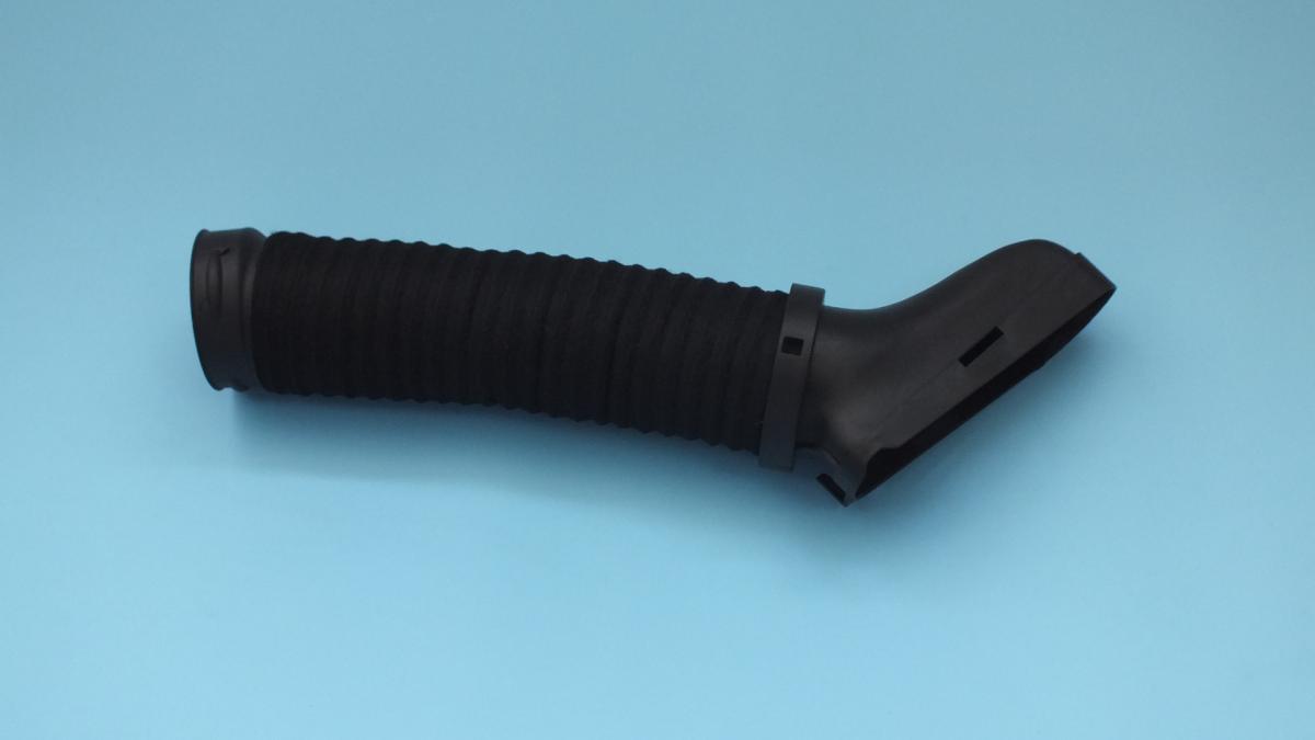
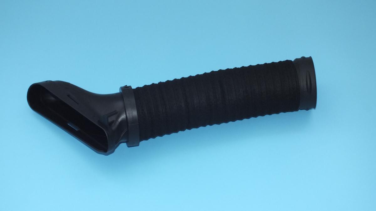
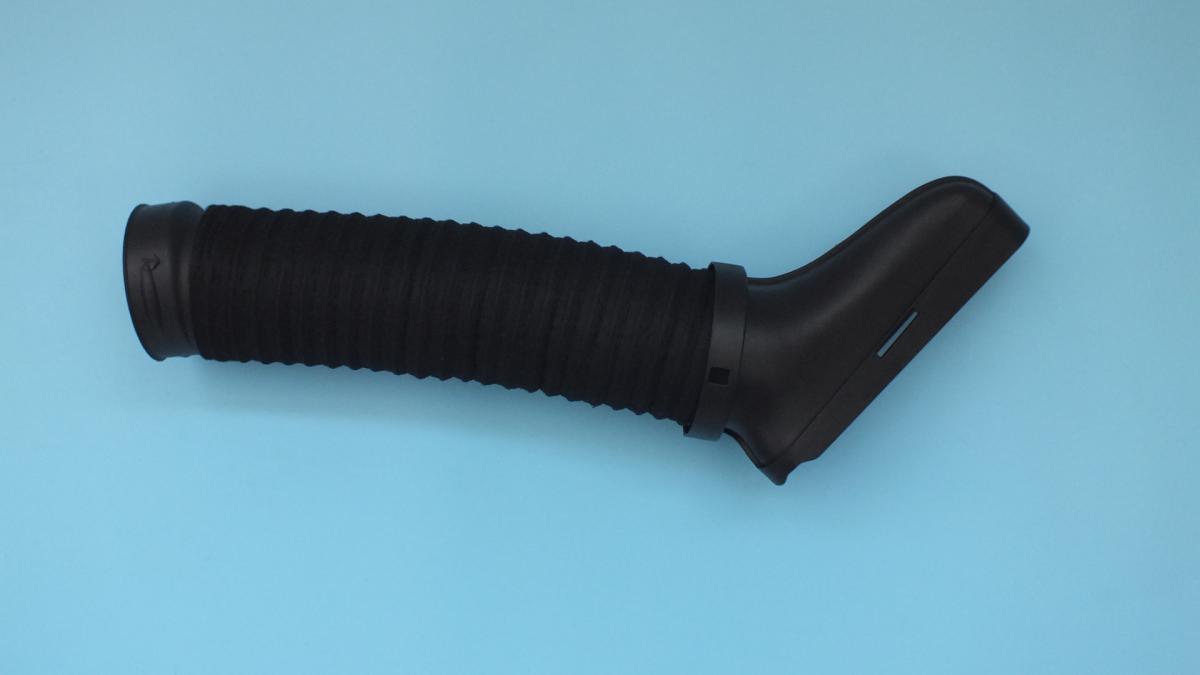
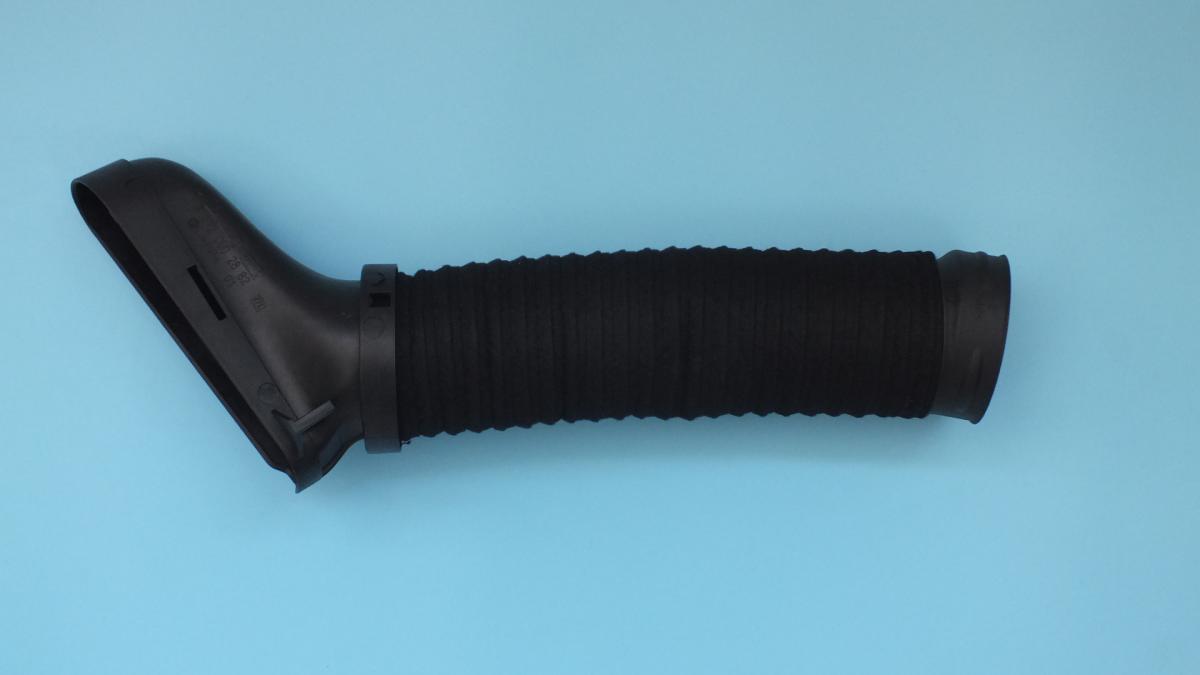
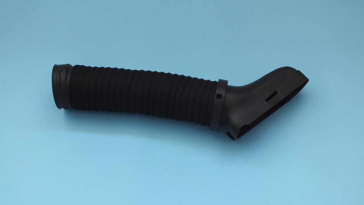
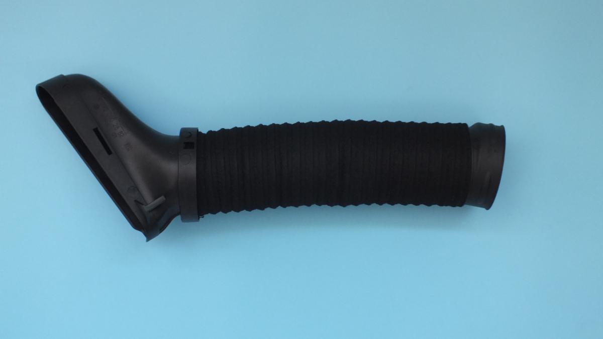
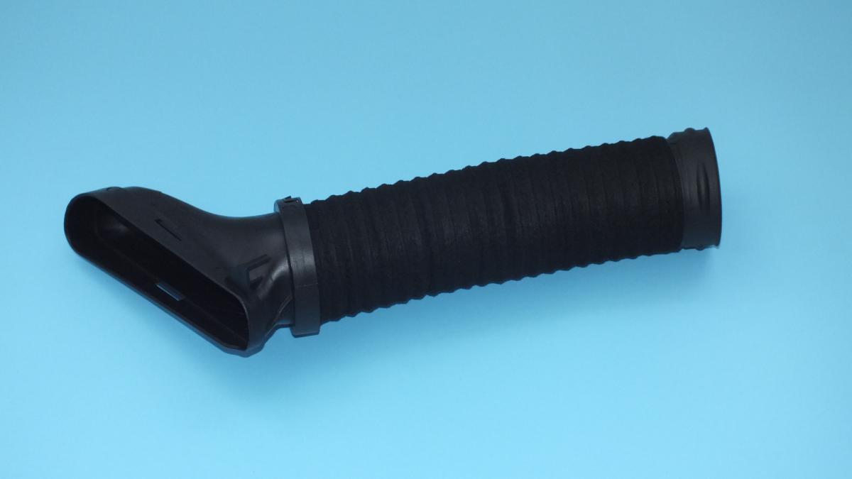
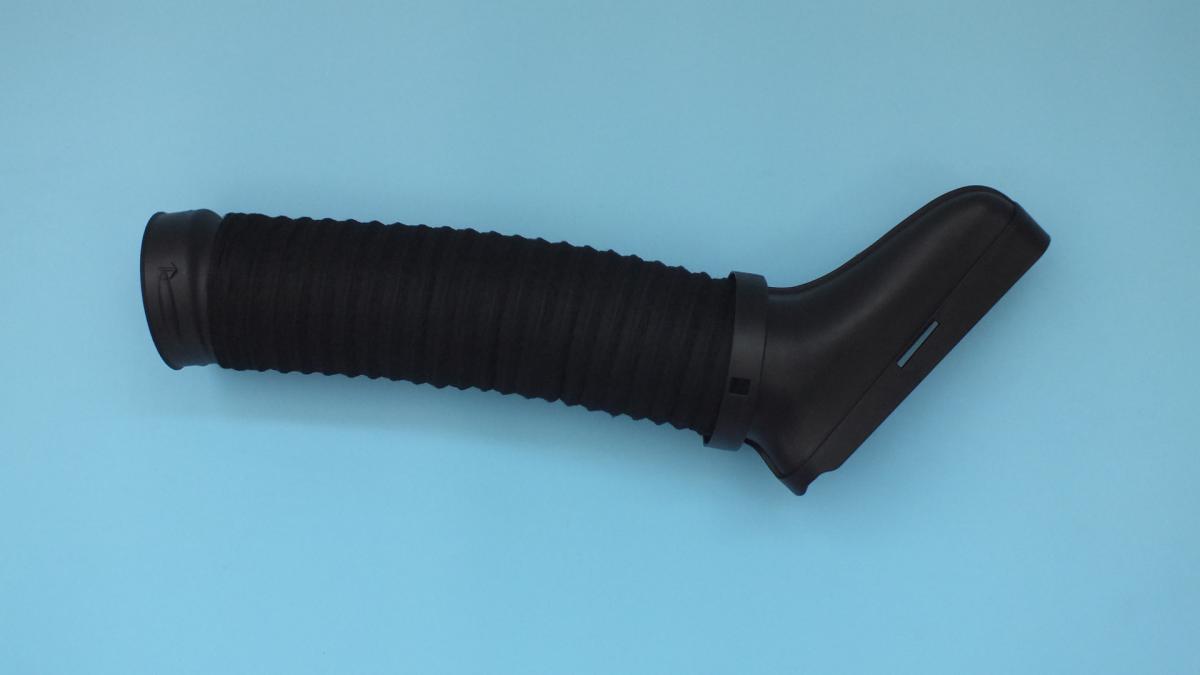
MERCEDES-BENZ A2720902882 INTAKE LINE
Product Specifications
| MERCEDES-BENZ | A2720902882 |
| MERCEDES-BENZ | 2720902882 |
| MERCEDES-BENZ | AIRDUCTRHTGLKX204 |
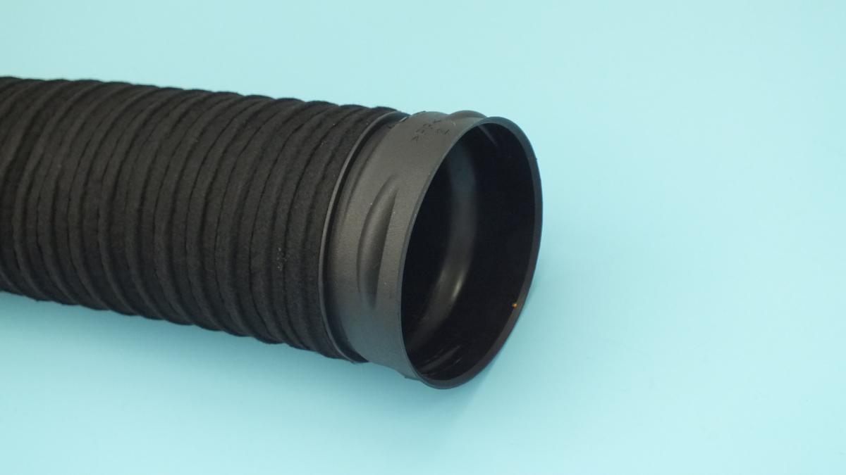
The INTAKE LINE is a moulded rubber, silicone, or thermoplastic elastomer air intake duct that forms the sealed conduit connecting the air filter housing to the mass airflow sensor, throttle body, or turbocharger compressor inlet, routing the measured airflow from the air filter to the engine's intake system while maintaining a completely sealed pathway that ensures the MAF sensor reads only filtered, measured air — any unmetered air that bypasses the duct between the air filter outlet and the throttle body entry point reaches the combustion chambers without being accounted for in the ECU's fuelling calculation, producing a lean mixture that the ECU cannot correct beyond its fuel trim limit. The intake duct's internal geometry is precisely designed for each engine application to minimise pressure drop and turbulence in the airflow approaching the MAF sensor — a sensor that reads turbulent, non-uniform flow produces an inaccurate airflow measurement that causes fuelling errors across the operating range; the duct's smooth internal bore and controlled bends maintain laminar flow conditions at the sensor element. On turbocharged engines the intake duct also serves as the low-pressure suction side of the turbocharger circuit — it must withstand the partial vacuum generated by the turbocharger compressor at full load without collapsing inward, while remaining flexible enough to accommodate engine movement on its mounts without cracking at the connection ends. Most designs incorporate a resonator chamber moulded into the duct wall or a separate resonator connected to the duct that attenuates induction noise from the intake valves at specific frequencies to meet the vehicle's interior noise targets.
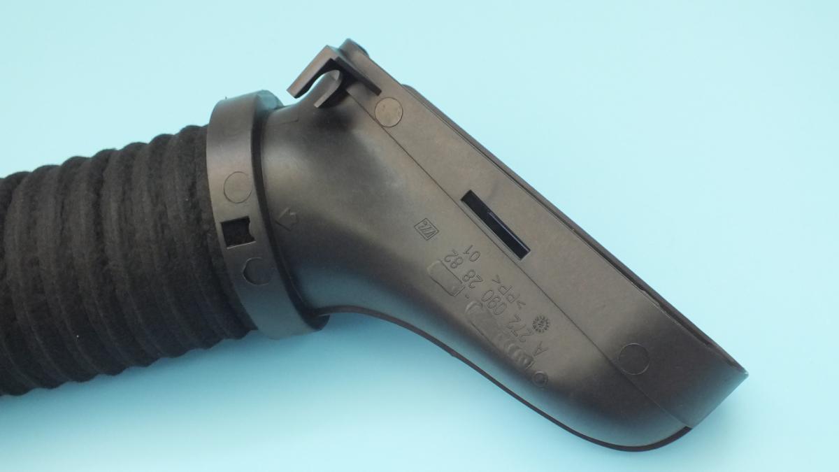
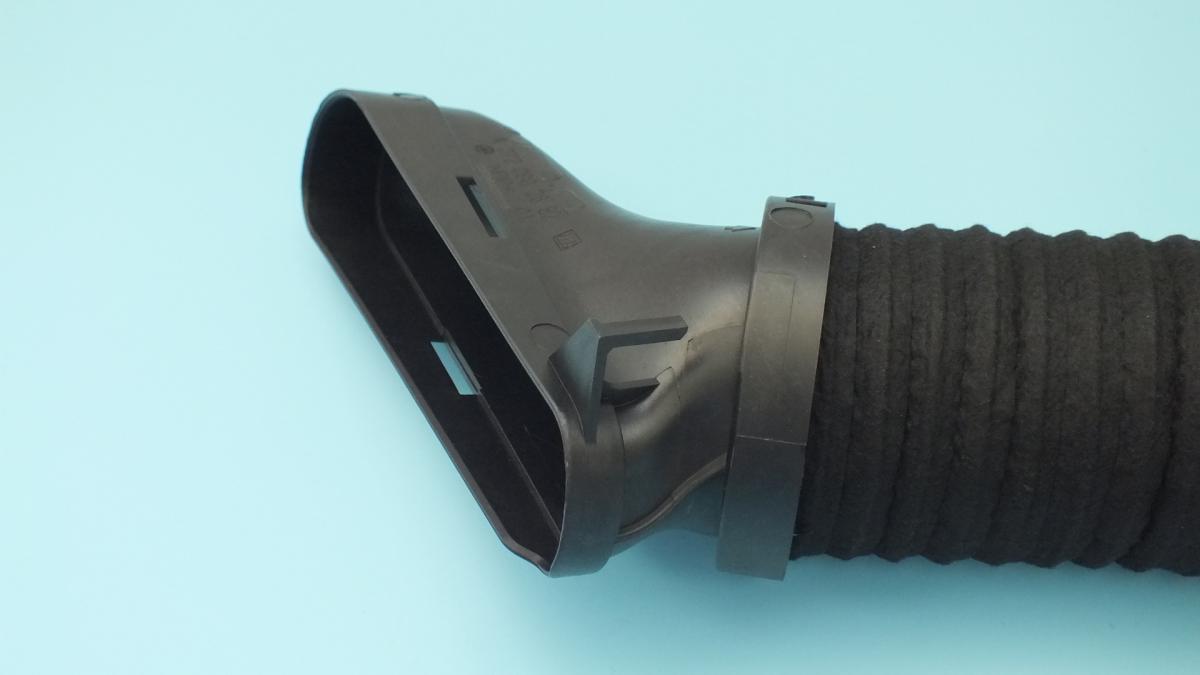
This unit — MERCEDES-BENZ A2720902882 — is manufactured to OEM-equivalent specifications: duct inner diameter at each connection point, overall length and curvature profile for the engine bay routing, wall thickness and material compound for the rated vacuum and temperature conditions, MAF sensor port geometry and orientation where the sensor mounts in the duct, crankcase ventilation hose connection port positions, resonator connection port geometry, and end fitting diameter and retention bead profile for the air filter housing and throttle body connections are matched to the original part. Supplied as a direct replacement for standard fitment. Available wholesale from 4.42 USD, MOQ 30 pcs, production lead time 42 days.
Air intake ducts fail through rubber or elastomer cracking from ozone, UV, and heat cycling — fine surface cracks that develop into through-cracks at connection end stress concentrations that admit unmetered air to the intake downstream of the MAF sensor; through internal collapse under turbocharger suction from material hardening that reduces the duct's resistance to vacuum; and through connection end tearing from the repeated removal forces applied during air filter servicing. A cracked intake duct is one of the most common and most misdiagnosed causes of lean mixture codes and rough idle on high-mileage vehicles, frequently leading to unnecessary replacement of the MAF sensor, oxygen sensor, or injectors before the duct crack is identified.
- Inspect the MAF sensor element and clean if oil-contaminated before installing the new duct — a cracked duct that has been drawing unmetered air may also have allowed rain water or engine bay contamination to contact the MAF sensor element; inspect the sensor's hot wire or film element for contamination deposits; clean with dedicated MAF sensor cleaner spray only — never contact the element physically; installing a new duct against a contaminated MAF sensor does not restore correct fuelling until the sensor is cleaned or replaced.
- Check all intake duct connection stubs — air filter housing outlet and throttle body or turbocharger inlet — for cracking and surface damage before fitting the new duct; a cracked stub on the air filter housing or throttle body that was the original source of the air leak will immediately produce the same lean mixture fault on the new duct; replace the housing or throttle body if the stub shows cracking that extends into the housing wall.
- Route the new duct following the OEM path exactly — photograph the original routing before removal; the intake duct must follow the OEM geometry to maintain the designed bend radii that prevent internal collapse under vacuum and to maintain the designed clearance from hot engine bay components; a duct rerouted with tighter bends than the OEM design will collapse at those bends under turbocharger suction load.
- Ensure all retention clips are fully seated in their designed groove positions on the connection stubs — worm-drive hose clamps on air intake ducts must be positioned over the bead or ridge on the connection stub rather than on the straight duct body; a clamp positioned on the straight section will slide under the pulsating vacuum of the intake cycle and allow the duct to pull partially off the stub, producing an intermittent air leak that is difficult to locate.
- Transfer all sensors, PCV hose connections, and resonator connections from the old duct to the new unit before installation — the MAF sensor, boost pressure sensor, and any other sensors mounted in the duct must be correctly seated in their ports on the new duct; a sensor not fully engaged in its port admits unmetered air around the sensor body; confirm each sensor is fully inserted and its retention clip is engaged before closing the engine cover.
- Install the new INTAKE LINE (MERCEDES-BENZ A2720902882), confirm all connections are secured, start the engine and use an OBD-II scanner to confirm the long-term fuel trim has returned toward zero from its previous positive correction value after a full warm-up cycle, confirm no lean codes are stored, and verify idle quality is smooth and stable before returning the vehicle to service.
| Part | Reason for Combined Replacement |
|---|---|
| Air Filter Element OEM ref. varies by engine air box | A cracked intake duct that has been drawing unfiltered air around the filter element may have allowed abrasive atmospheric particles to bypass the filter and reach the MAF sensor element, throttle body bore, and ultimately the engine's cylinder bores. Replacing the air filter simultaneously with the duct ensures the new duct operates with a fresh filter from the first moment, and provides an opportunity to inspect the filter housing interior for signs of unfiltered air contamination that would require housing cleaning or replacement. |
| Mass Airflow Sensor OEM ref. varies by engine | An intake duct crack that has been present for an extended period will have exposed the MAF sensor element to turbulent, non-uniform flow and potentially to contamination from the unfiltered air side. A MAF sensor that has been operating with incorrect airflow conditions may have developed a calibration drift that persists even after the duct is replaced and the airflow is restored to its correct laminar profile. If fuel trims do not return toward zero after duct replacement, clean the MAF sensor with dedicated cleaner; if trims remain positive after cleaning, the sensor requires replacement. |
| Throttle Body OEM ref. varies by engine | An intake duct that has been cracked for significant mileage may have allowed oil mist from the crankcase ventilation connection to coat the throttle body bore and plate with a sticky varnish that partially restricts airflow and affects idle control. With the intake duct removed for replacement, inspect the throttle body bore for deposits and clean with throttle body cleaner if any build-up is present; a heavily deposited throttle body that does not clean effectively requires replacement to restore correct idle airflow control. |