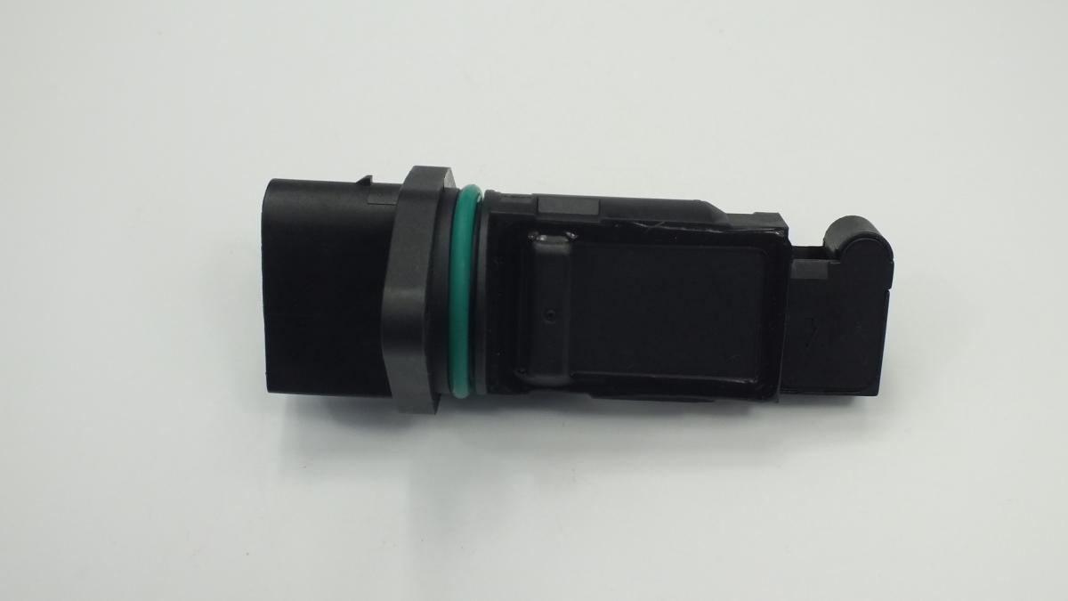
MERCEDES-BENZ A6460940048 MASS AIR FLOW SENSOR
Product Specifications
| MERCEDES-BENZ | A6460940048 |
| MERCEDES-BENZ | A0000941048 |
| MERCEDES-BENZ | A1120940048 |
| MERCEDES-BENZ | A1130940048 |
| MERCEDES-BENZ | A0000941448 |
| MERCEDES-BENZ | A0000940948 |
| MERCEDES-BENZ | A0000941948 |
| MERCEDES-BENZ | A0041530628 |
| MERCEDES-BENZ | A0041537328 |
| MERCEDES-BENZ | A000094094880 |
| MERCEDES-BENZ | A000094104880 |
| MERCEDES-BENZ | A646094004880 |
| MERCEDES-BENZ | A112094004880 |
| MERCEDES-BENZ | 6460940048 |
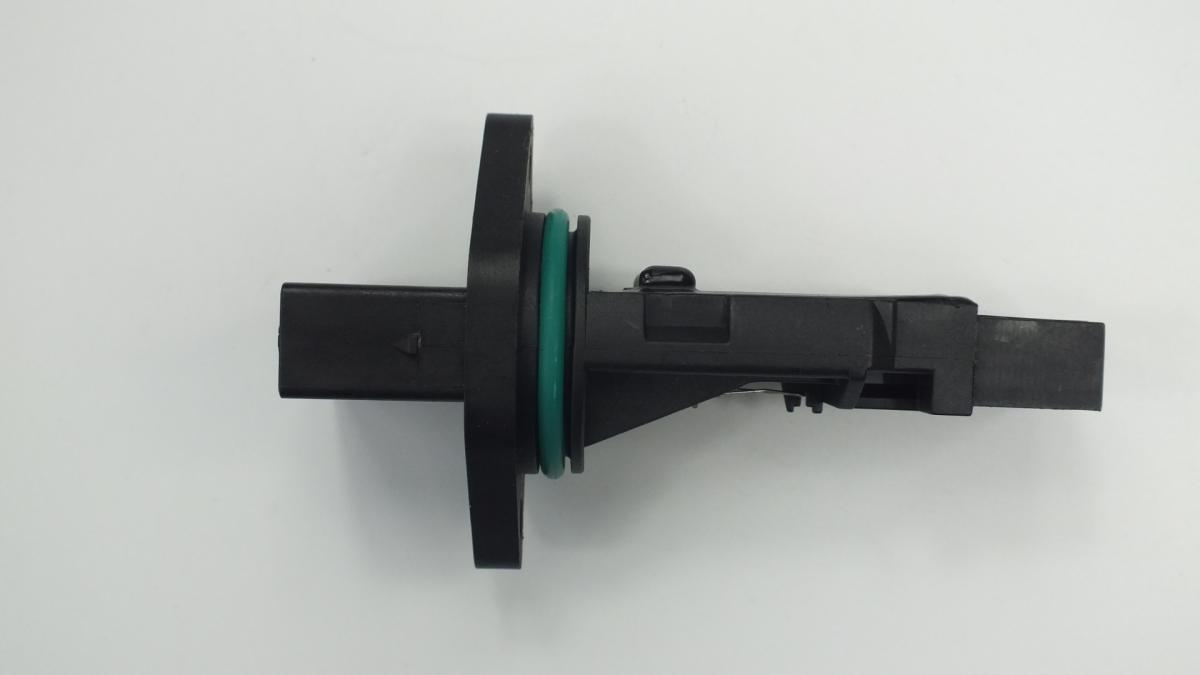
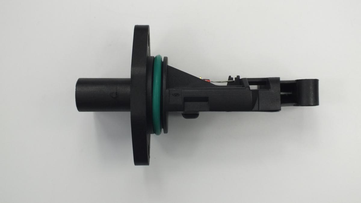
The MASS AIR FLOW SENSOR is a hot-wire or hot-film anemometer installed in the intake air duct between the air filter housing and the throttle body that measures the mass flow rate of air entering the engine in real time, providing the ECU with the primary load signal used to calculate injector pulse width, ignition timing, EGR rate, and turbocharger boost target. The sensing element consists of a platinum hot-wire or thin-film resistor heated to a precise temperature above ambient — typically 100–170°C above the incoming air temperature — by a constant-temperature control circuit; as airflow increases, heat is carried away from the element at a higher rate, requiring more current to maintain the setpoint temperature, and this current demand is converted to a voltage or frequency output proportional to mass airflow. Modern MAF sensors integrate an intake air temperature sensor in the same housing, providing the ECU with both mass flow and charge temperature in a single unit, since air density — and therefore the oxygen mass available for combustion — varies with both flow rate and temperature.
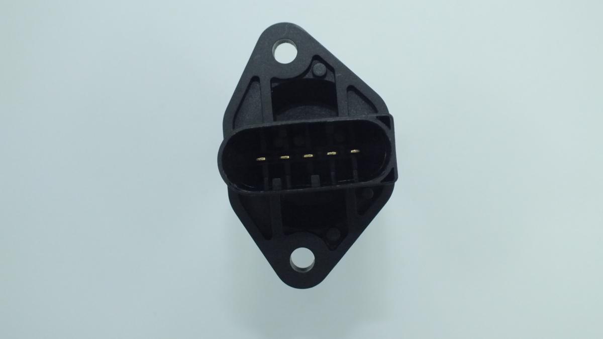
This unit — MERCEDES-BENZ A6460940048 — is manufactured to OEM-equivalent specifications: sensing element resistance and temperature coefficient, output signal type and voltage range at idle and maximum flow, housing bore diameter and insertion depth, integrated air temperature sensor calibration curve, and connector pinout are matched to the original part. Supplied as a direct plug-and-play replacement for standard fitment. Available wholesale from 8.27 USD, MOQ 100 pcs, production lead time 52 days.
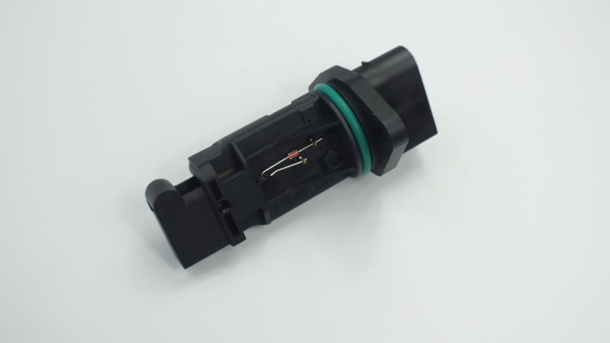
MAF sensors fail through contamination of the sensing element by oil vapour from the crankcase breather system depositing a film that insulates the wire thermally and causes the sensor to under-read airflow, mechanical damage to the fragile sensing wire from reversed airflow during backfires, and electronic circuit failure within the sensor housing. A MAF sensor that has drifted low — reading less air than is actually entering the engine — causes the ECU to calculate a lean base fuelling that the closed-loop lambda correction partially compensates, masking the fault until the correction limit is exceeded. Always inspect and replace the air filter and check for intake duct cracks before fitting a new MAF sensor, as contamination sources and unmetered air leaks will degrade the new sensor within a short operating period.
- Identify and eliminate the contamination source before fitting the new sensor — inspect the crankcase breather hose and oil separator for evidence of oil vapour passage; if the breather hose outlet is immediately upstream of the MAF sensor position, a saturated oil separator is coating the sensing element with oil mist. Fitting a new sensor without addressing the oil vapour source will contaminate it within a few thousand kilometres.
- Inspect the entire intake duct from the air filter to the throttle body for cracks, splits, and loose clamps before removing the MAF sensor — an air leak downstream of the MAF sensor allows unmetered air into the engine, causing the same lean fuel trim fault codes as a failed sensor; replacing the sensor without sealing the duct leak will not resolve the fault code.
- Never touch the sensing element wire or film inside the MAF sensor housing at any point during handling or installation — the hot-wire element is a platinum wire of 70–100 microns diameter that will be permanently damaged by contact with a fingertip, tool, or cleaning cloth; handle the sensor by its housing body only and keep the element end pointed away from surfaces.
- Use only dedicated MAF sensor cleaner spray if cleaning is attempted before condemning a sensor — apply the cleaner to the element from a distance of at least 15 cm with the sensor removed from the duct, allow to evaporate completely for a minimum of 30 minutes before reinstalling, and never use compressed air, carburettor cleaner, or brake cleaner near the element as these damage the sensing element coating or bend the wire.
- Fit the sensor in the correct orientation — the arrow or airflow direction marking on the sensor housing must align with the direction of airflow from the air filter to the engine; a reversed MAF sensor produces a near-zero output as the element is on the downstream face and senses turbulent wake rather than laminar flow, causing immediate limp-home mode on startup.
- Install the new MASS AIR FLOW SENSOR (MERCEDES-BENZ A6460940048), reconnect the electrical connector until it clicks, refit the intake duct clamps and tighten to specification, start the engine and allow it to reach operating temperature, then use a scan tool to confirm the live MAF reading in g/s is within the known-good range for the engine at idle and at 2,500 RPM before clearing fault codes and performing a fuel trim reset.