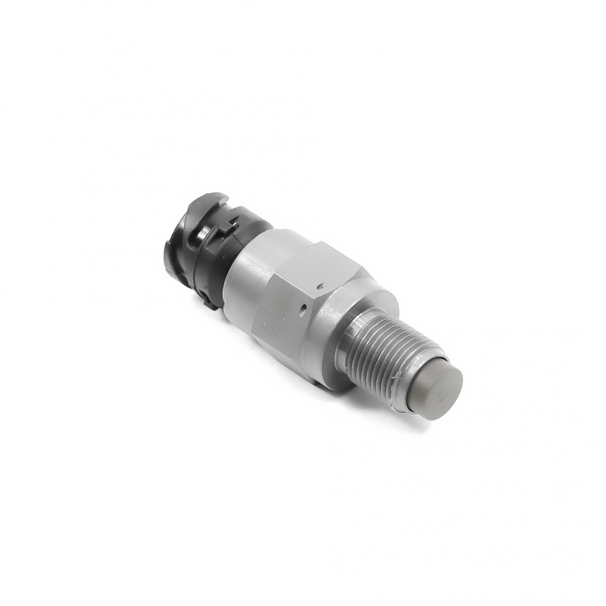
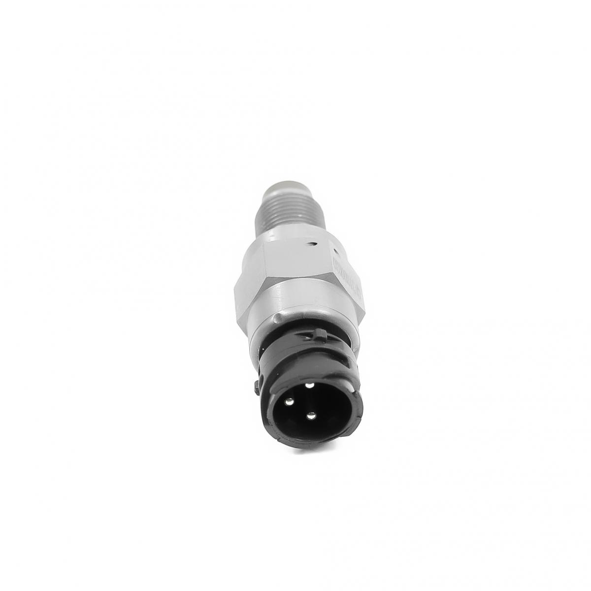
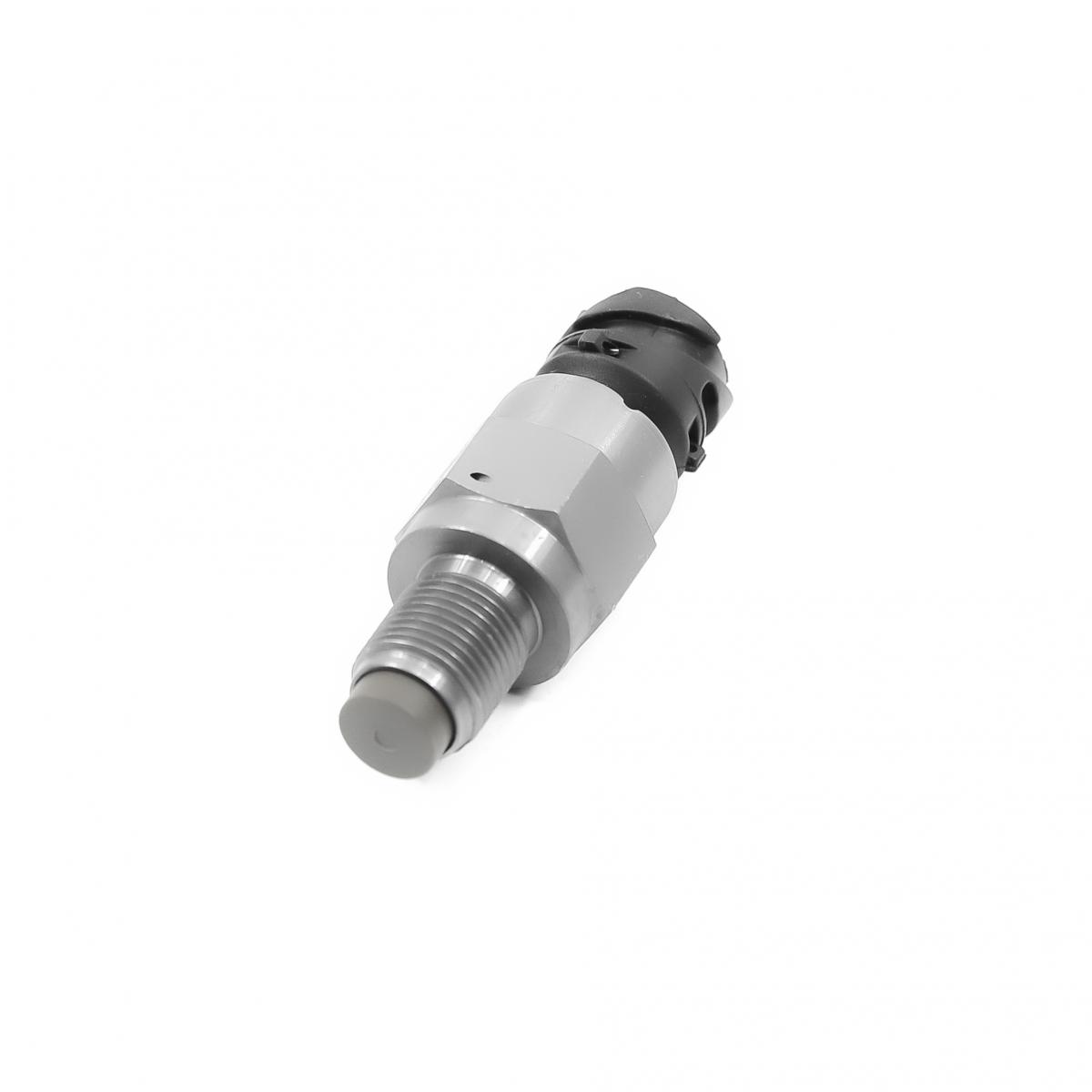
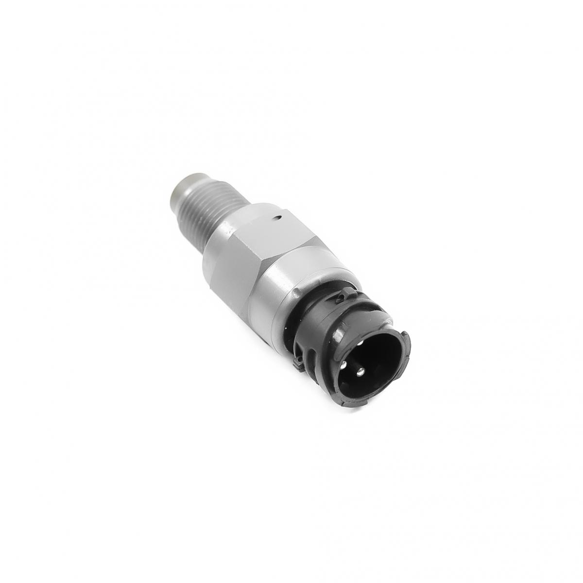
MERCEDES-BENZ A155422717 SPEED SENSOR
Product Specifications
| MERCEDES-BENZ | A155422717 |
| MERCEDES-BENZ | A0155422717 |
| MERCEDES-BENZ | A0135426717 |
| MERCEDES-BENZ | 155422717 |
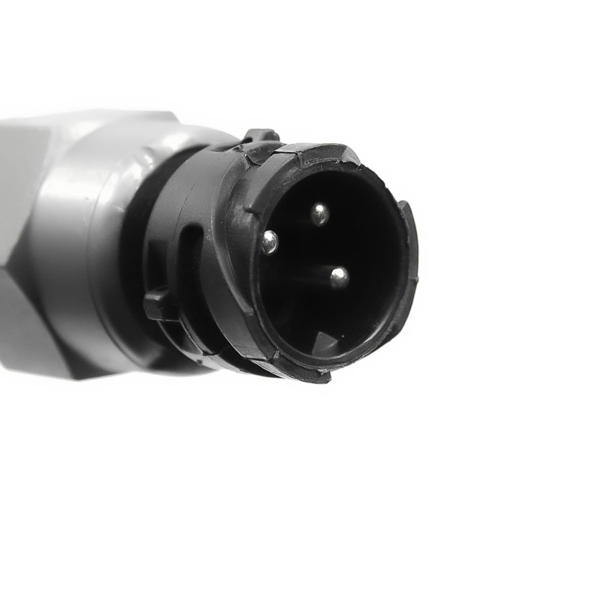
The SPEED SENSOR is a magnetic or Hall-effect sensor that measures the rotational speed of a toothed reluctor ring on the transmission output shaft, differential, or driveshaft and converts this rotation into a pulsed electrical signal whose frequency is proportional to vehicle road speed, providing the ECU, ABS module, instrument cluster, and transmission control module with real-time vehicle speed data for fuel injection management, automatic transmission shift point calculation, speedometer display, ABS and stability control operation, and cruise control function. Passive variable-reluctance (VR) speed sensors generate a self-powered sinusoidal AC voltage from the interaction of the sensor's permanent magnet and the passing reluctor teeth — amplitude and frequency both increase with rotational speed; the signal requires no power supply and is processed by the receiving module's zero-crossing detection circuit. Active Hall-effect speed sensors require a 5V or 12V supply and produce a clean digital square-wave output whose frequency is independent of signal amplitude, allowing accurate measurement at very low vehicle speeds approaching zero — essential for ABS wheel lock detection and automatic transmission creep management that VR sensors cannot reliably provide at near-zero speed.
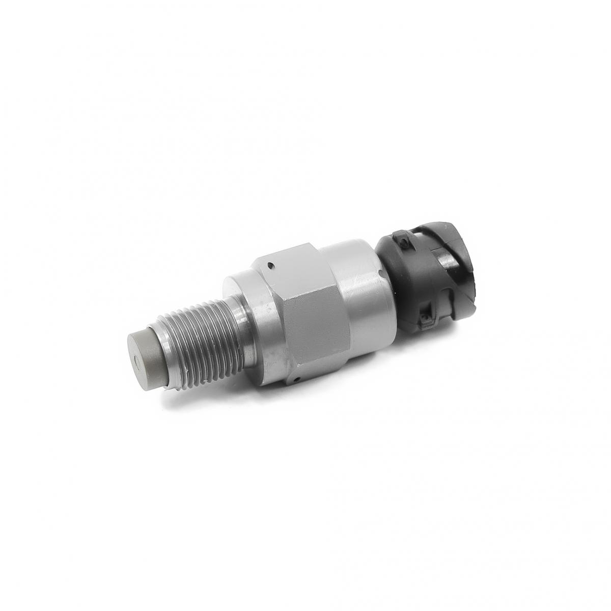
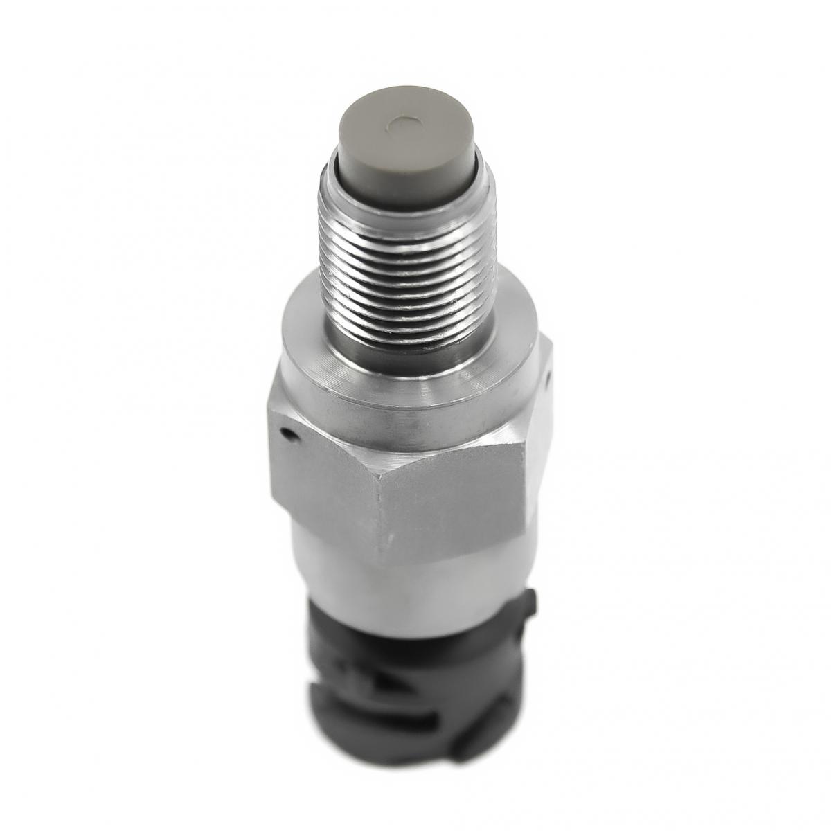
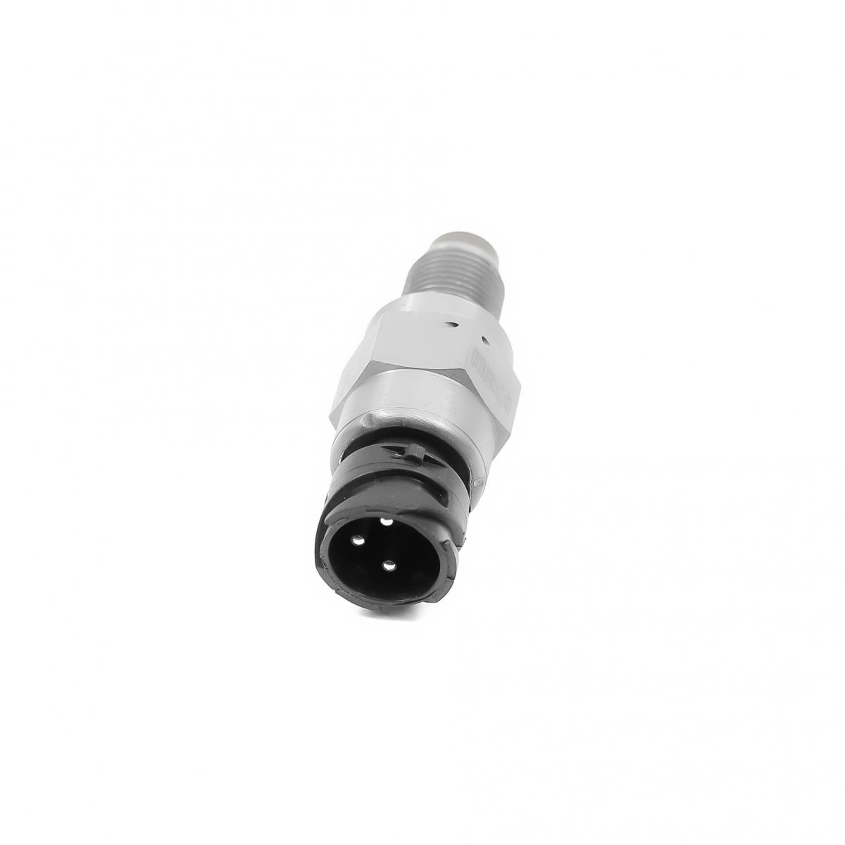
This unit — MERCEDES-BENZ A155422717 — is manufactured to OEM-equivalent specifications: sensor type (VR or Hall-effect), output signal frequency per tooth pass, supply voltage and current draw where applicable, air gap specification between sensor tip and reluctor ring, housing thread size or mounting flange geometry, connector pinout, and operating temperature range are matched to the original part. Supplied as a direct plug-and-play replacement for standard fitment. Available wholesale from 4.95 USD, MOQ 20 pcs, production lead time 44 days.
Speed sensors fail through internal magnet or Hall element degradation, connector pin corrosion from the underbody moisture and road salt environment in which they operate, physical damage to the sensor tip from contact with the reluctor ring caused by worn transmission output shaft bearings that allow the shaft to deflect under load, and wiring harness chafing at bracket contact points. Before replacing a speed sensor, always inspect the reluctor ring for damaged or missing teeth and verify the air gap between the sensor tip and the ring — a reluctor ring with broken teeth produces the same erratic speed signal as a failed sensor, and a sensor installed with an incorrect air gap will produce a weak or absent signal regardless of its internal condition.
- Read and record all stored fault codes with an OBD-II scanner before disconnecting the sensor — the fault code description identifies the specific sensor circuit by location (output shaft, front left wheel, etc.) and failure mode (open circuit, short, range); this information is essential to confirm the correct replacement sensor is being fitted and is lost on some platforms when the battery is disconnected.
- Verify supply voltage and ground at the sensor connector with a multimeter before removing the sensor — an active Hall-effect sensor with correct supply voltage that produces no output has failed internally; the same sensor with no supply voltage has a wiring fault between the connector and the control module that will not be resolved by replacing the sensor; always confirm the electrical circuit is intact before condemning the sensor body.
- Inspect the reluctor ring for damaged, missing, or cracked teeth before fitting the new sensor — a reluctor ring with one or more broken teeth produces an erratic speed signal with periodic drop-outs at the tooth-pass frequency that is identical in presentation to a failing sensor; a new sensor will produce the same erratic signal on a damaged reluctor ring; replace the ring if any tooth damage is found.
- Clean the sensor mounting bore and measure the air gap between the sensor tip and reluctor ring after installing the new sensor — use a non-magnetic feeler gauge to confirm the gap is within the OEM specification, typically 0.2–1.5 mm depending on the sensor type; a VR sensor installed outside the specified gap produces a signal too weak for the module's zero-crossing detector at low speeds; a Hall-effect sensor is less gap-sensitive but still requires a minimum clearance to avoid tip contact with the ring.
- Route the sensor wiring harness in all original clip positions with adequate slack at the sensor body to accommodate any drivetrain movement — a harness pulled tight against the sensor connector will fracture the internal pins under driveline vibration within a short period; secure the harness away from rotating shafts, exhaust components, and sharp edges that could chafe through the insulation.
- Install the new SPEED SENSOR (MERCEDES-BENZ A155422717), torque to OEM specification, reconnect the connector, clear all stored fault codes with the scan tool, drive the vehicle through a full speed range from 0 to 100 km/h, and confirm the speed reading on the scan tool live data matches GPS speed and that no fault codes return before returning the vehicle to service.
| Part | Reason for Combined Replacement |
|---|---|
| Reluctor Ring / Tone Wheel OEM ref. varies — output shaft or wheel hub | A reluctor ring with cracked, chipped, or missing teeth produces the same erratic speed signal as a failed sensor — a fault that cannot be resolved by replacing the sensor alone. Inspect the reluctor ring whenever a speed sensor is replaced; if tooth damage is found, replace the ring simultaneously. A damaged ring will destroy the new sensor's signal quality from the first revolution and cause immediate return of the same fault code. |
| Wiring Harness Repair Kit Application-specific connector and seal kit | Speed sensor connectors are located in the underbody environment and are subject to pin corrosion, connector locking tab fracture, and harness insulation cracking from road salt and thermal cycling. A connector with corroded pins produces intermittent speed signal faults that are indistinguishable from sensor internal failure until the connector is inspected. Replace the connector and any chafed harness section simultaneously with the sensor to prevent the same fault from recurring on the new unit within a short period. |
| Transmission Output Shaft Bearing OEM ref. varies by transmission type | A speed sensor that has failed due to physical tip damage — visible as a scored or ground-off sensor face — has been destroyed by contact with the reluctor ring caused by excessive output shaft radial deflection from a worn output shaft bearing. Replacing only the sensor without addressing the bearing allows the new sensor to be destroyed by the same contact within a short operating period. If tip damage is found on the failed sensor, measure output shaft bearing play before fitting the replacement. |