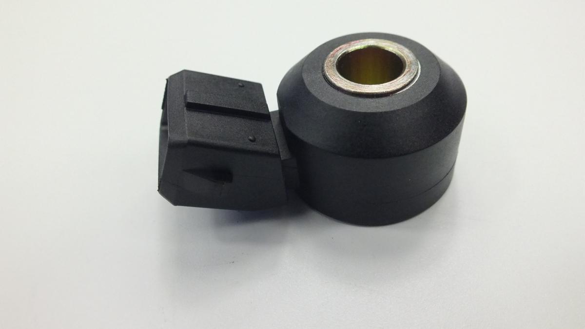
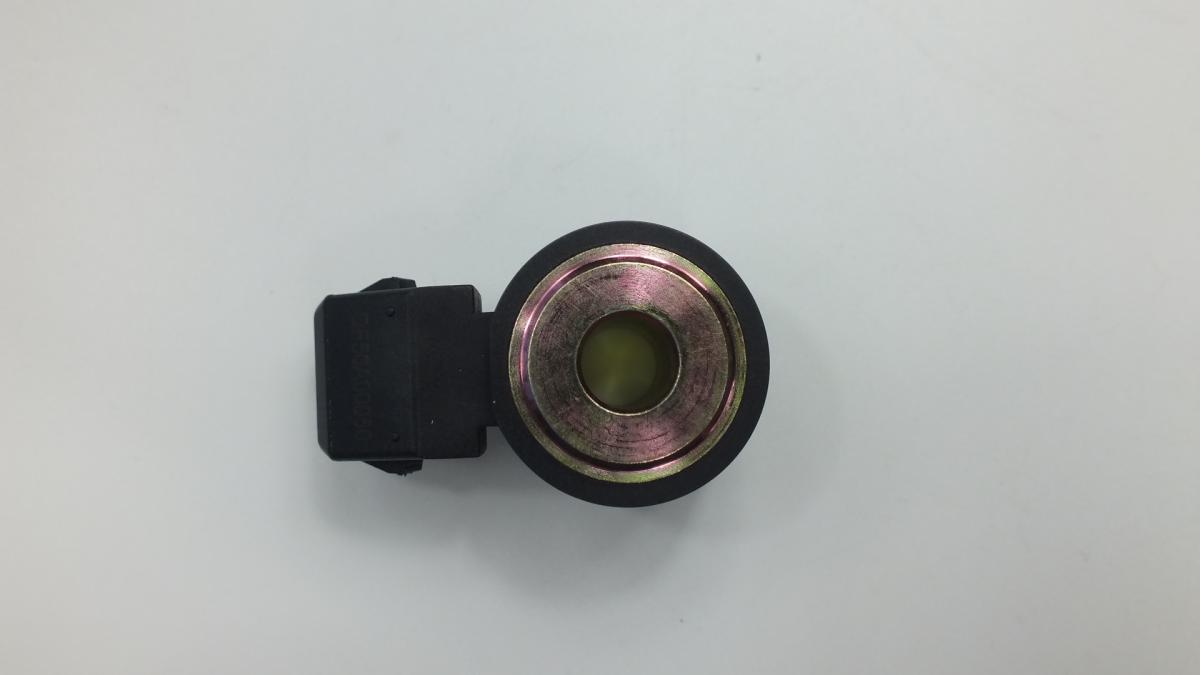
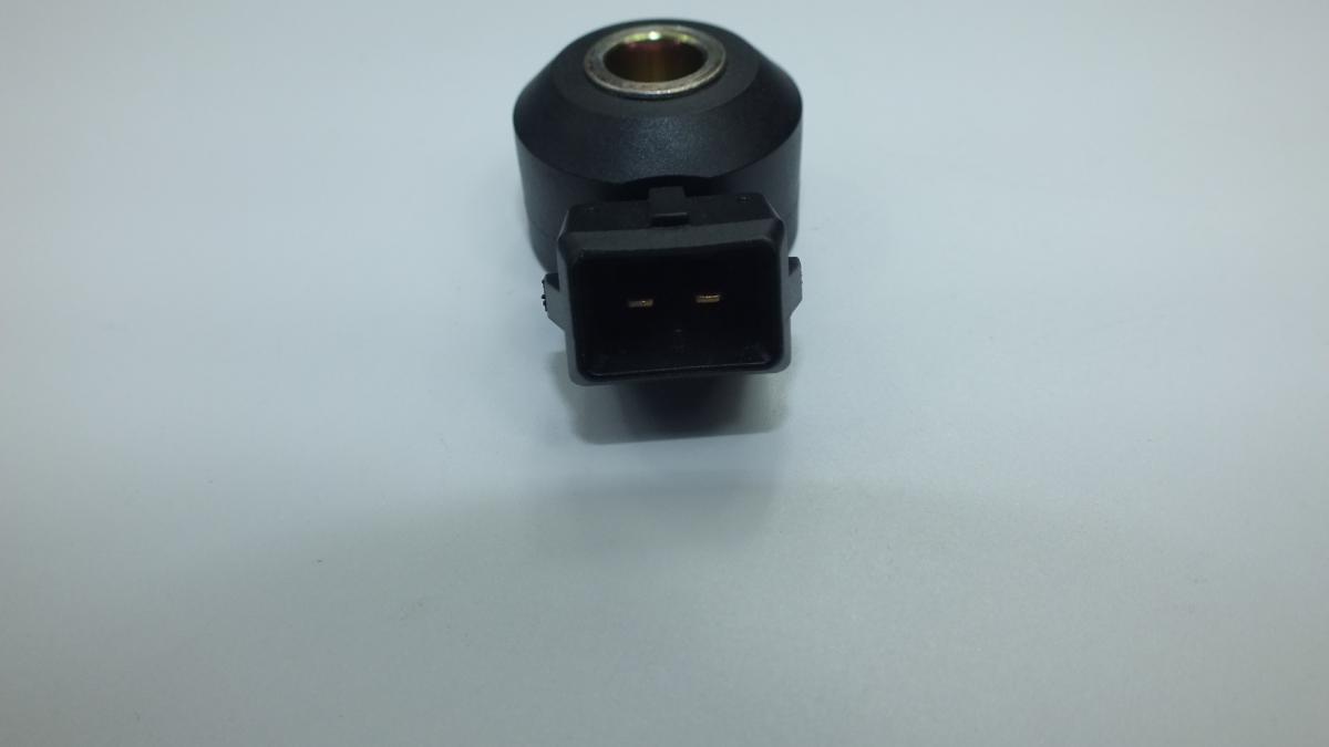
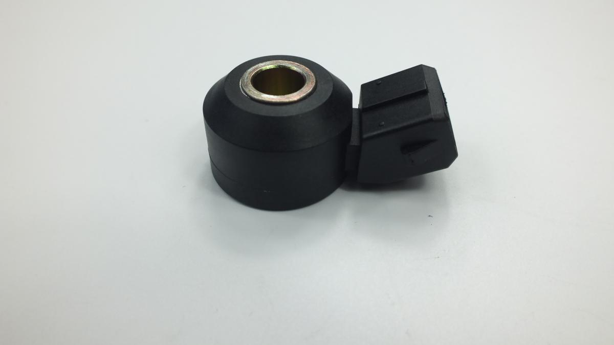
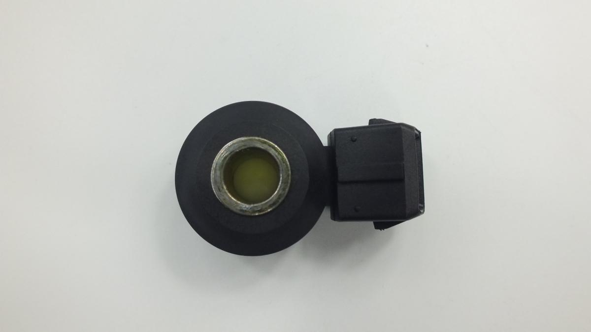
BMW/MINI 13627598861 KNOCK SENSOR
Product Specifications
| BMW/MINI | 13627598861 |
The KNOCK SENSOR is a piezoelectric vibration sensor bolted directly to the engine block or cylinder head that detects the characteristic high-frequency structural vibration signature of combustion knock — the uncontrolled auto-ignition of the end-gas charge ahead of the propagating flame front — and transmits this signal to the ECU, which uses it to retard ignition timing on the affected cylinder until the knock event ceases, then advances timing back toward the optimum point in a continuous closed-loop process that maximises thermal efficiency while protecting the engine from the mechanical damage that sustained knock produces. The sensor element is a piezoelectric ceramic disc that generates a voltage output proportional to the mechanical stress applied to it; when knock occurs, the pressure wave from the uncontrolled combustion event propagates through the engine structure as a high-frequency vibration at 5–15 kHz — the characteristic knock frequency band — that stresses the piezoelectric element and produces a distinctive voltage burst that the ECU's knock detection circuit filters from background engine vibration using a bandpass filter tuned to the knock frequency range for the specific engine. The ECU monitors knock on a cylinder-individual basis by correlating the sensor signal's timing with each cylinder's power stroke, allowing it to retard timing selectively on only the knocking cylinder rather than applying a global timing retard that would penalise all cylinders for knock in one.
This unit — BMW/MINI 13627598861 — is manufactured to OEM-equivalent specifications: piezoelectric element sensitivity and resonant frequency, sensor body dimensions and mounting bolt hole diameter, output signal connector pinout, shielded cable length where applicable, and operating temperature range are matched to the original part. Supplied as a direct replacement for standard fitment. Available wholesale from 2.57 USD, MOQ 10 pcs, production lead time 34 days.
Knock sensors fail through piezoelectric element cracking from overtightening the mounting bolt — the ceramic element is mechanically pre-stressed by the correct mounting torque to optimise its sensitivity; overtightening crushes the element beyond its design limit and fractures it, producing either no output or an abnormally high constant output; through connector pin corrosion from underbonnet moisture that increases signal circuit resistance and reduces the sensor's effective output voltage; and through element sensitivity drift from sustained thermal cycling at engine block temperatures above the sensor's rated limit. A failed knock sensor causes the ECU to apply a fixed maximum ignition timing retard as a protective measure — the engine will not knock but runs with measurably reduced power and increased fuel consumption while the fault persists.
- Test the wiring harness for continuity and insulation resistance between the sensor connector and the ECU connector before fitting the new sensor — a break in the shielded signal cable or a short to ground in the harness will produce the same knock sensor fault code on the new sensor as on the original; use a multimeter to confirm signal wire continuity and confirm no short between signal wire and shield or ground before installing the replacement; replacing a serviceable sensor into a faulty harness wastes cost and does not resolve the fault code.
- Clean the sensor mounting boss on the engine block meticulously — remove all rust, debris, and old thread lock compound from the boss face and mounting thread with a wire brush and brake cleaner; any debris under the sensor body prevents uniform contact between the sensor base and the block surface, altering the mechanical coupling between the block and the piezoelectric element and reducing the sensor's ability to detect knock vibration accurately.
- Torque the mounting bolt to the OEM specification using a torque wrench — this is the single most critical step in knock sensor installation — the piezoelectric element's sensitivity is calibrated for the design mechanical pre-stress imposed by the correct mounting torque, typically 15–25 Nm depending on the engine; undertightening produces insufficient pre-stress and reduces sensitivity; overtightening by even 30% above specification crushes and fractures the ceramic element, destroying the new sensor before the engine is started; always use a torque wrench — never tighten by feel.
- Do not apply thread lock compound to the mounting bolt unless specifically required by the OEM — thread lock changes the friction coefficient of the thread, altering the relationship between torque wrench reading and actual bolt clamping force; on knock sensor mounting bolts where the clamping force directly determines the sensor's sensitivity, a thread lock application without a corresponding torque correction produces an incorrectly pre-stressed element even when the correct torque value is applied.
- Route the sensor cable away from ignition HT leads, ignition coils, and the alternator output wire — the knock sensor signal is a low-amplitude millivolt-level output that is extremely sensitive to electromagnetic interference from these sources; a cable routed in contact with an HT lead or coil primary wire picks up ignition interference that the ECU interprets as knock events, causing the ECU to retard timing unnecessarily on every ignition cycle; use the original cable routing clips and maintain the OEM separation distance from interference sources.
- Install the new KNOCK SENSOR (BMW/MINI 13627598861), reconnect the shielded cable connector until it clicks, clear all knock sensor fault codes with an OBD-II scanner, start the engine and run to operating temperature, confirm the fault code does not return, and verify on scan tool live data that the knock sensor signal shows a low-level alternating output that responds to engine load changes before returning the vehicle to service.
| Part | Reason for Combined Replacement |
|---|---|
| Knock Sensor Wiring Harness Shielded signal cable — application-specific | The knock sensor signal cable carries a millivolt-level output that is uniquely vulnerable to electromagnetic interference from adjacent ignition components. The shielded cable's outer braid provides the electromagnetic isolation that keeps the signal clean — a cable with a damaged shield or a break in the shielding continuity allows ignition interference to contaminate the signal and produce phantom knock events that cause the ECU to retard timing unnecessarily. If the existing cable shows heat damage, chafing, or a damaged connector boot, replace it simultaneously with the sensor to provide the new sensor with an interference-free signal path. |
| Spark Plugs OEM specification — complete engine set | A failed knock sensor that has been applying maximum timing retard as a protective default has also been preventing the engine from knocking — the retarded timing reduced thermal efficiency but protected the engine. If the engine has been operating with a fault code on a knock sensor for a significant mileage, inspect the spark plugs for signs of pre-ignition damage — a white or blistered insulator tip indicates the timing retard was insufficient to prevent all abnormal combustion events. Replace plugs showing thermal damage simultaneously with the sensor to restore the complete ignition system to a known serviceable condition. |
| Ignition Coils COP coil set — application-specific | On engines where the knock sensor fault has been present for an extended period, the ECU's timing retard has increased ignition coil primary current demand as the coils charge to a higher voltage against the retarded combustion cycle. Coils that have been operating under this elevated demand show accelerated insulation fatigue. If the vehicle has accumulated significant mileage with an active knock sensor fault code, inspect the coils for carbon tracking and resistance drift simultaneously with the sensor replacement. |