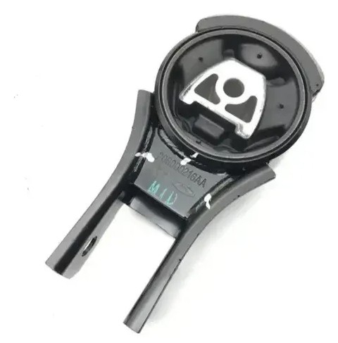
CHERY 206000216AA ENGINE MOUNT
Product Specifications
| CHERY | 206000216AA |
The Chery 206000216AA is an Engine Mount (Powertrain Mount) for Chery passenger vehicle applications — vibration-isolating structural component securing engine + transmission to subframe / body, absorbing powertrain torque reaction and preventing engine vibration from transmitting in cabin. Construction: steel inner sleeve bonded to outer steel bracket via vulcanised rubber element providing multi-axis compliance; some Chery applications use hydraulic mounts adding fluid-filled damping chamber for additional attenuation at idle resonant frequencies.
Engine mount performs four functions: (1) static support — carries fraction of powertrain weight (100-300 kg per mount across 3-4 positions); (2) vibration isolation — rubber element acts as low-pass mechanical filter, attenuating high-frequency engine vibration (firing-order 25-200 Hz) before transmission to body; (3) torque reaction control — resists powertrain roll under acceleration while allowing controlled compliance; (4) impact protection — in frontal collision, mount network fails in controlled manner contributing to crumple-zone energy absorption.
Typical transverse-engine vehicle uses 3-4 mount positions: right-side mount (timing-belt end, largest load-bearing), left-side / transmission mount, rear pendulum / torque rod / dog-bone mount (rotational control), and optional front roll-restrictor mount at lower subframe. Each position has different bracket geometry, durometer, OEM reference — verifying mount position by OEM on existing failed mount essential before ordering.
Mounts degrade through rubber oxidation from heat exposure, oil contamination from valve / rocker cover gasket leaks (softens rubber), accumulated fatigue from torque loading, and impact damage from pothole / kerb strikes. Collapsed mount allows excessive powertrain movement loading adjacent mounts disproportionately — sequential mount failures within months common.
| International HS Code | 4016.99 |
| EAEU Customs Code (TN VED) | 4016 99 970 9 |
| Country of Manufacture | China |
| Quality standard | IATF 16949 |
| Hazardous goods | No |
| Packaging | Individual cardboard packaging with vehicle application label and protective foam corner pieces |
Engine mounts as rubber-bonded vibration isolators are typically classified under HS 4016.99 (other articles of vulcanised rubber other than hard rubber). Some jurisdictions classify under HS 8708.99 (other parts of motor vehicles) for the steel-bracket assembly. Confirm the exact 10-digit subheading and applicable duty rates with your customs broker. Commercial invoice description: engine mount / powertrain vibration isolator for passenger vehicle, vulcanised rubber-bonded element with steel bracket assembly.
Chery passenger vehicle range using 2060-prefix engine mounts (verify exact match by OEM number before ordering): Tiggo series (Tiggo 4, Tiggo 5x, Tiggo 7, Tiggo 7 Pro, Tiggo 8, Tiggo 8 Pro, Tiggo 9 with Pro / Plus / Pro Max variants), Arrizo sedan series (Arrizo 5, Arrizo 6, Arrizo 8), Omoda crossovers (Omoda 5, Omoda 7), Jaecoo SUVs (Jaecoo J7, Jaecoo J8), Fulwin new-energy variants. Documented neighbouring references in the same series include 206000191AA / 206000192AA (Rear Engine Mount, Arrizo 6) and 206000569AA / 206000596AA / 206000100AA / 206000119AA / 206000117AA / 206000096AA / 206000097AA (Engine Suspension cushions and brackets, Tiggo 7 / 8 Pro 1.6T) — these provide platform context but are NOT direct cross-references for 206000216AA. The 206000216AA may apply to one of these vehicles or a different platform / position; the supplier should confirm exact applicability before order.
Does NOT fit: Any Chery vehicle whose existing engine mount does not have 206000216AA stamped on the bracket / casting label. Despite similar physical appearance, engine mounts are non-interchangeable between Chery platforms / positions due to: (1) different bracket geometry matching the platform's specific engine bay layout; (2) different bolt patterns; (3) different rubber durometer matched to the platform's powertrain weight and engine torque rating; (4) hydraulic vs rubber-only construction differences. Always verify before ordering.
Difficulty: Moderate. Estimated time: 60–120 minutes per mount depending on position and access. The engine must be supported externally before any mount is removed — allowing the engine to hang on the remaining mounts loads them beyond design and may damage them, requiring additional mount replacement.
- 1Identify the failed mount and verify the OEM number before disassembly. Photograph the mount in situ and the surrounding cable / hose routing for reference during reassembly. Order any additional mounts that show degradation alongside the primary failed unit.
- 2Park on a level surface with engine cool. Open the bonnet. Disconnect the negative battery terminal if working near electrical connections.
- 3Support engine externally: (a) hydraulic jack with wood block under oil sump; (b) engine support bar (bolted to strut towers); (c) engine crane hooked to lifting point. Never allow engine to hang on remaining mounts.
- 4Remove any obstructing components — air filter housing, intake duct, heat shield, brake fluid reservoir bracket, coolant reserve tank bracket, depending on the mount position being serviced. Photograph removal sequence for refit.
- 5Remove mount-to-subframe bolts first, then mount-to-engine bracket bolts. Apply penetrating oil to seized fasteners + allow soak time. Use breaker bar for stubborn bolts (subframe bolts torqued 80-120 Nm).
- 6Raise engine slightly with support jack to relieve mount load + create extraction clearance. 10-30 mm lift typical. Watch for hose / cable / pipe interference — coolant hoses, fuel lines, harness may need repositioning.
- 7Extract the old mount from its position. Inspect for confirming failure mode (rubber crack location, oil saturation depth, hydraulic fluid leak, bracket deformation). Address oil leak sources before installing the new mount.
- 8Compare the new mount to the old one — verify bracket geometry matches, bolt hole pattern matches, overall dimensions match, rubber element orientation marked correctly. For hydraulic mounts, confirm the fluid chamber is intact (no visible leakage) and the unit is orientated correctly per any directional markings.
- 9Position the new mount in place and start ALL bolts by hand before torquing any of them — this allows alignment correction and prevents thread cross-threading. Lower the engine slowly using the support jack to its natural resting position.
- 10Torque ALL fasteners with engine at natural resting position, NOT under jack load (pre-stresses rubber, reduces service life). OEM spec: typically 60-100 Nm mount-to-subframe; 40-60 Nm mount-to-engine bracket. Consult Chery service manual for your specific position.
- 11Refit any obstructing components removed for access. Verify all hoses, cables, and pipes are routed correctly without contact with the new mount. Reconnect the battery if disconnected.
- 12Road test in safe area: clunk eliminated; idle vibration reduced; no new abnormal noise; engine in correct position under acceleration. Hydraulic mount: allow several heat / cool cycles before final assessment — damping develops over first 100-200 km.
| Part | Reference | Reason for Combined Replacement |
|---|---|---|
| Adjacent Engine Mounts (Right / Left / Rear) | Chery 2060XXXXX-AA series for the matching vehicle / position | Engine + transmission mounts age at same rate, share powertrain load. Failed mount transfers load to adjacent units during failure period, accelerating wear. Inspect all mounts during service; replace any showing degradation simultaneously. Vehicles >120,000 km benefit from full set replacement. |
| Torque Rod / Pendulum / Dog-Bone Mount | Chery powertrain torque arm reference, application-specific | Many transverse-engine Chery vehicles use torque rod / dog-bone mount to control longitudinal movement under acceleration. Works in conjunction with main mounts, bears significant rotational load. Inspect during main mount service; replace if cracking / separation / excessive deflection. Failure produces same clunk symptom but during acceleration only. |
| Valve Cover / Cam Cover Gasket | Chery valve cover gasket, engine-specific reference | Oil leak from valve cover is primary cause of rubber mount degradation. If failed mount showed oil saturation, valve cover gasket leaking onto mount. Replacement without addressing oil leak shortens new mount life 5-10x. Address valve cover gasket simultaneously. |
| Mount Retention Bolts (TTY where applicable) | Chery mount bolt set, position-specific | Some Chery mount retention bolts are torque-to-yield (TTY) single-use fasteners that lose clamp-load spec after original install. Reusing TTY bolts produces incorrect mount preload, may allow movement that destroys new mount. Consult Chery service manual for your specific position. |
| Transmission Mount Cushion | Chery transmission mount, application-specific | If failed mount on engine end (right typically), transmission mount on opposite end (left typically) has been bearing additional load. Inspect during service; replace if visible degradation. Particularly relevant if original symptom included transmission gear-engagement clunk. |