PEUGEOT/CITROËN 252927 SWITCH
Product Specifications
| PEUGEOT/CITROËN | 252927 |
| PEUGEOT/CITROËN | 7700100010 |
| PEUGEOT/CITROËN | 1635684480 |
| RENAULT | 7700100010 |
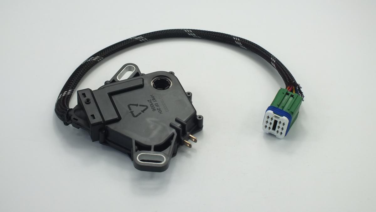
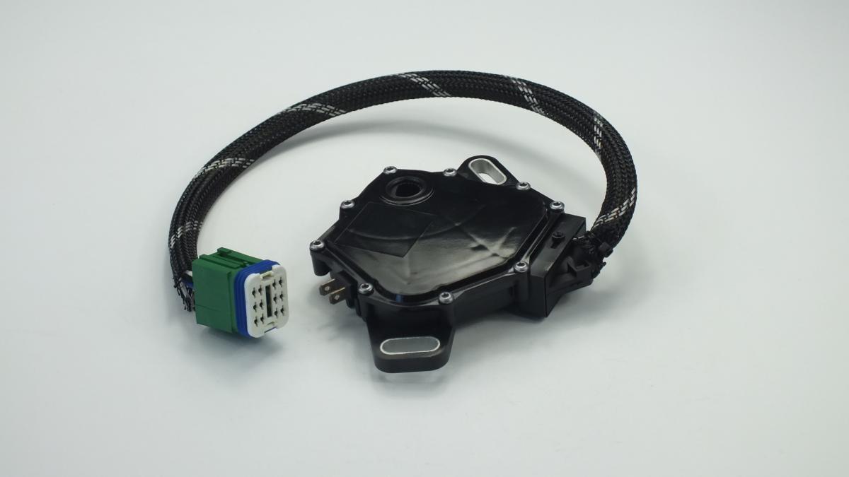
The SWITCH is an automotive switch or sensor unit that detects a specific mechanical state — a button press, a pedal position, a gear selector position, a lever engagement, or a rotary input — and converts that state into an electrical signal that commands a corresponding function in the vehicle's electrical or electronic control system. Automotive switches and position sensors of this class share a common operating principle regardless of the specific function they serve: a set of normally-open or normally-closed electrical contacts — either mechanical contacts in a simple switch or a variable resistance, Hall-effect, or reed switch element in a sensor — changes state when the actuating condition is met, signalling the relevant control module or directly switching a circuit. Examples within this product category include the brake light switch that closes when the brake pedal is depressed to illuminate the stop lamps and signal the ABS and ESC modules; the reverse light switch that closes when reverse gear is engaged to activate the reversing lamps and the PDC system; the 4WD engagement switch that signals the transfer case control module to lock the centre differential; the transmission range sensor that communicates PRNDL selector position to the TCU and instrument cluster; the boot release button that signals the BCM to energise the boot latch actuator; and the mirror control switch that routes left-right-up-down joystick inputs to the mirror adjustment motors.
This unit — PEUGEOT/CITROËN 252927 — is manufactured to OEM-equivalent specifications: contact material and rated current capacity, actuation force and travel, housing dimensions and mounting geometry for correct installation position, electrical connector pinout, signal type (normally-open, normally-closed, or variable resistance), and operating temperature and ingress protection rating are matched to the original part. Supplied as a direct plug-and-play replacement for standard fitment. Available wholesale from 8.55 USD, MOQ 1000 pcs, production lead time 39 days.
Switches and position sensors of this type fail through contact oxidation from moisture ingress that increases contact resistance until the controlled function becomes intermittent or stops entirely; through mechanical wear of the actuating plunger or pivot at high cycle count positions such as the brake pedal switch; through connector pin corrosion in exposed underbonnet or transmission tunnel locations; and through internal circuit board cracking from vibration in sensors mounted directly on the transmission or transfer case. The most reliable diagnostic sequence for any failed switch is to confirm supply voltage at the connector, measure switch output signal before and after actuation, and compare against specification — this three-step sequence locates the fault in the switch, the wiring, or the controlled circuit without misdiagnosis.
- Confirm supply voltage and ground at the connector before removing the switch — a switch fault diagnosis that has not verified the supply circuit may result in replacing a serviceable switch while the actual fault is a broken supply wire, blown fuse, or failed relay; apply a 12V test light or multimeter to the supply and ground pins of the connector with the ignition on before disconnecting anything; only proceed with switch replacement when supply and ground are confirmed correct.
- Disconnect the battery negative terminal before removing switches located in the passenger compartment or in proximity to airbag modules — switches near the steering column, centre console, and door panels are in the SRS deployment zone; inadvertent contact with airbag wiring during switch replacement can trigger accidental airbag deployment; always observe the SRS discharge wait time specified by the OEM — typically 60–90 seconds after battery disconnection — before working in the deployment zone.
- Note the exact installation position, depth, and orientation of the removed switch before extraction — transmission range sensors, reverse light switches, and 4WD engagement switches installed at an incorrect depth or rotational angle produce a signal offset that causes the module to report the wrong position or no signal; photograph the switch installation position from multiple angles before removal; some position sensors require a specific installation angle verified with an alignment mark or pin.
- Clean the switch mounting threads and bore with the correct tap or thread chaser before fitting the new switch where the switch screws into a threaded boss — transmission-mounted switches are subject to corrosion from gearbox oil and road salt that builds up in the thread; cross-threading a new switch into a corroded boss destroys the housing thread and may require housing replacement; clean threads first, hand-thread the new switch through its full engagement before applying a torque wrench.
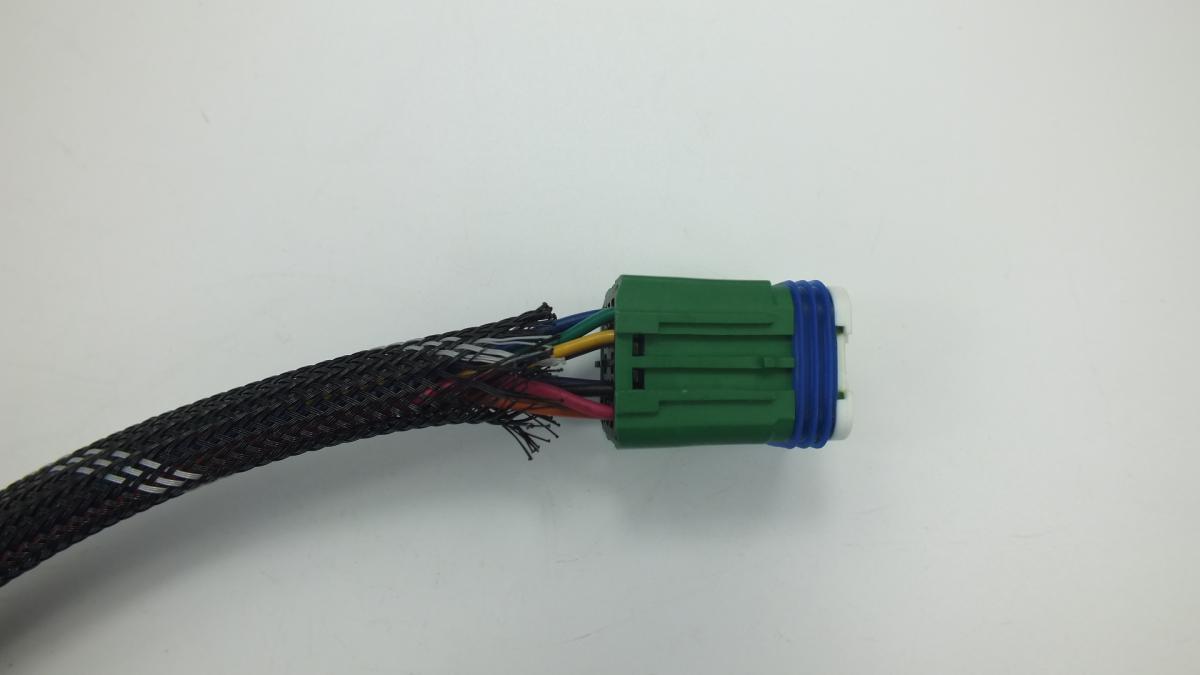
- Inspect the wiring connector for pin corrosion, bent pins, damaged sealing grommet, and broken locking tab before connecting to the new switch — a corroded connector that caused the original switch failure through high-resistance contact will immediately begin degrading the new switch's performance; clean corroded pins with electrical contact cleaner; a connector with a broken locking tab that allowed moisture ingress must be repaired or replaced before the new switch is connected.
- Install the new SWITCH (PEUGEOT/CITROËN 252927), reconnect the battery, clear all stored fault codes with a scan tool, and functionally test every operating state of the switch — confirm the controlled function activates and deactivates correctly at every switch position, verify no warning lights remain, and on position sensors confirm the instrument cluster or scan tool live data shows the correct position reading for each selector or lever state before returning the vehicle to service.
| Part | Reason for Combined Replacement |
|---|---|
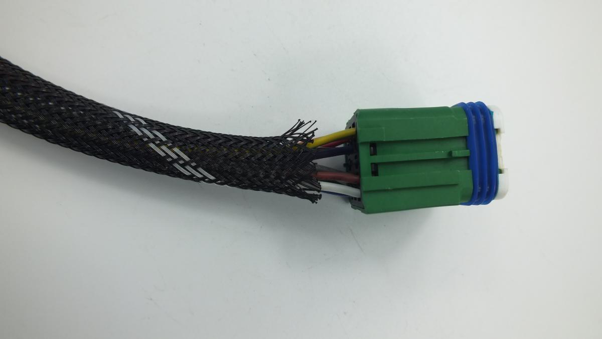
| Wiring Harness Connector Application-specific connector and seal | The wiring connector at the switch is the most common cause of switch circuit faults — corroded or bent pins produce the same intermittent fault signature as a failed switch contact and are frequently misdiagnosed as switch failure. If the connector shows pin corrosion, a cracked sealing grommet, or a broken locking tab when the old switch is removed, replace the connector simultaneously with the new switch to prevent the same contact resistance fault from reappearing on the new unit within a short operating period. |
| Related Switch in the Same Circuit Paired or redundant switch — application-specific | Some vehicle systems use two switches to provide redundancy or to separately control related functions — the clutch pedal switch on manual transmission vehicles has both a starter inhibit contact and a cruise control cancel contact in the same housing; the brake pedal switch has a primary stop lamp contact and a secondary ABS/ESC input contact. If one contact set of a dual-function switch has failed, the second contact set has accumulated the same wear and is approaching the same failure point; replacing the complete switch assembly addresses both simultaneously. |
| Fuse and Relay for the Controlled Circuit Application-specific fuse rating and relay type | A switch that has been failing intermittently with high contact resistance may have subjected the circuit fuse and relay to repeated voltage spike events from the arcing contacts. While the fuse and relay are unlikely to have failed from normal switch wear, inspecting them simultaneously with the switch replacement adds negligible time and confirms the complete circuit is in serviceable condition before the new switch is installed — an undetected faulty relay that fails shortly after switch replacement requires a repeat diagnostic session. |
PEUGEOT/CITROËN 252927 SWITCH
Product Specifications
| PEUGEOT/CITROËN | 252927 |
| PEUGEOT/CITROËN | 7700100010 |
| PEUGEOT/CITROËN | 1635684480 |
| RENAULT | 7700100010 |
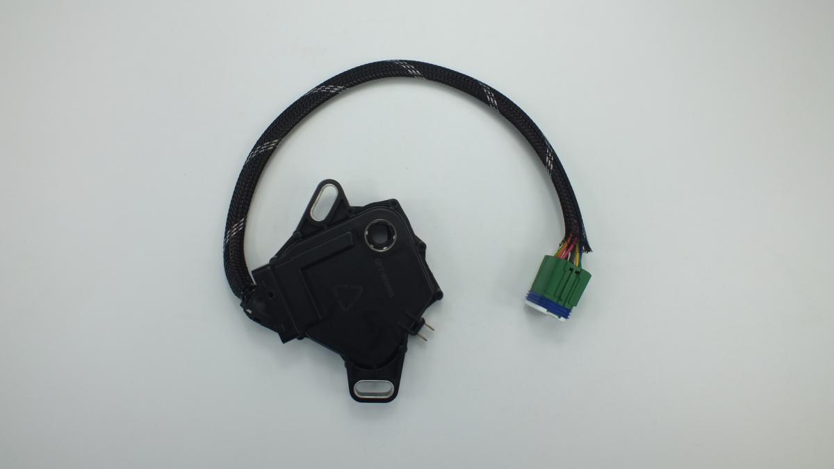
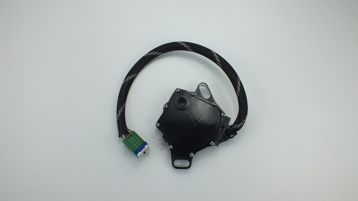
The SWITCH is an automotive switch or sensor unit that detects a specific mechanical state — a button press, a pedal position, a gear selector position, a lever engagement, or a rotary input — and converts that state into an electrical signal that commands a corresponding function in the vehicle's electrical or electronic control system. Automotive switches and position sensors of this class share a common operating principle regardless of the specific function they serve: a set of normally-open or normally-closed electrical contacts — either mechanical contacts in a simple switch or a variable resistance, Hall-effect, or reed switch element in a sensor — changes state when the actuating condition is met, signalling the relevant control module or directly switching a circuit. Examples within this product category include the brake light switch that closes when the brake pedal is depressed to illuminate the stop lamps and signal the ABS and ESC modules; the reverse light switch that closes when reverse gear is engaged to activate the reversing lamps and the PDC system; the 4WD engagement switch that signals the transfer case control module to lock the centre differential; the transmission range sensor that communicates PRNDL selector position to the TCU and instrument cluster; the boot release button that signals the BCM to energise the boot latch actuator; and the mirror control switch that routes left-right-up-down joystick inputs to the mirror adjustment motors.
This unit — PEUGEOT/CITROËN 252927 — is manufactured to OEM-equivalent specifications: contact material and rated current capacity, actuation force and travel, housing dimensions and mounting geometry for correct installation position, electrical connector pinout, signal type (normally-open, normally-closed, or variable resistance), and operating temperature and ingress protection rating are matched to the original part. Supplied as a direct plug-and-play replacement for standard fitment. Available wholesale from 8.55 USD, MOQ 1000 pcs, production lead time 39 days.
Switches and position sensors of this type fail through contact oxidation from moisture ingress that increases contact resistance until the controlled function becomes intermittent or stops entirely; through mechanical wear of the actuating plunger or pivot at high cycle count positions such as the brake pedal switch; through connector pin corrosion in exposed underbonnet or transmission tunnel locations; and through internal circuit board cracking from vibration in sensors mounted directly on the transmission or transfer case. The most reliable diagnostic sequence for any failed switch is to confirm supply voltage at the connector, measure switch output signal before and after actuation, and compare against specification — this three-step sequence locates the fault in the switch, the wiring, or the controlled circuit without misdiagnosis.
- Confirm supply voltage and ground at the connector before removing the switch — a switch fault diagnosis that has not verified the supply circuit may result in replacing a serviceable switch while the actual fault is a broken supply wire, blown fuse, or failed relay; apply a 12V test light or multimeter to the supply and ground pins of the connector with the ignition on before disconnecting anything; only proceed with switch replacement when supply and ground are confirmed correct.
- Disconnect the battery negative terminal before removing switches located in the passenger compartment or in proximity to airbag modules — switches near the steering column, centre console, and door panels are in the SRS deployment zone; inadvertent contact with airbag wiring during switch replacement can trigger accidental airbag deployment; always observe the SRS discharge wait time specified by the OEM — typically 60–90 seconds after battery disconnection — before working in the deployment zone.
- Note the exact installation position, depth, and orientation of the removed switch before extraction — transmission range sensors, reverse light switches, and 4WD engagement switches installed at an incorrect depth or rotational angle produce a signal offset that causes the module to report the wrong position or no signal; photograph the switch installation position from multiple angles before removal; some position sensors require a specific installation angle verified with an alignment mark or pin.
- Clean the switch mounting threads and bore with the correct tap or thread chaser before fitting the new switch where the switch screws into a threaded boss — transmission-mounted switches are subject to corrosion from gearbox oil and road salt that builds up in the thread; cross-threading a new switch into a corroded boss destroys the housing thread and may require housing replacement; clean threads first, hand-thread the new switch through its full engagement before applying a torque wrench.
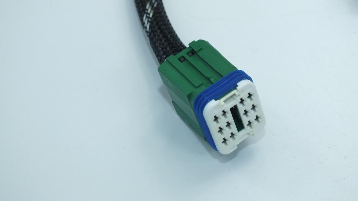
- Inspect the wiring connector for pin corrosion, bent pins, damaged sealing grommet, and broken locking tab before connecting to the new switch — a corroded connector that caused the original switch failure through high-resistance contact will immediately begin degrading the new switch's performance; clean corroded pins with electrical contact cleaner; a connector with a broken locking tab that allowed moisture ingress must be repaired or replaced before the new switch is connected.
- Install the new SWITCH (PEUGEOT/CITROËN 252927), reconnect the battery, clear all stored fault codes with a scan tool, and functionally test every operating state of the switch — confirm the controlled function activates and deactivates correctly at every switch position, verify no warning lights remain, and on position sensors confirm the instrument cluster or scan tool live data shows the correct position reading for each selector or lever state before returning the vehicle to service.
| Part | Reason for Combined Replacement |
|---|---|
| Wiring Harness Connector Application-specific connector and seal | The wiring connector at the switch is the most common cause of switch circuit faults — corroded or bent pins produce the same intermittent fault signature as a failed switch contact and are frequently misdiagnosed as switch failure. If the connector shows pin corrosion, a cracked sealing grommet, or a broken locking tab when the old switch is removed, replace the connector simultaneously with the new switch to prevent the same contact resistance fault from reappearing on the new unit within a short operating period. |
| Related Switch in the Same Circuit Paired or redundant switch — application-specific | Some vehicle systems use two switches to provide redundancy or to separately control related functions — the clutch pedal switch on manual transmission vehicles has both a starter inhibit contact and a cruise control cancel contact in the same housing; the brake pedal switch has a primary stop lamp contact and a secondary ABS/ESC input contact. If one contact set of a dual-function switch has failed, the second contact set has accumulated the same wear and is approaching the same failure point; replacing the complete switch assembly addresses both simultaneously. |
| Fuse and Relay for the Controlled Circuit Application-specific fuse rating and relay type | A switch that has been failing intermittently with high contact resistance may have subjected the circuit fuse and relay to repeated voltage spike events from the arcing contacts. While the fuse and relay are unlikely to have failed from normal switch wear, inspecting them simultaneously with the switch replacement adds negligible time and confirms the complete circuit is in serviceable condition before the new switch is installed — an undetected faulty relay that fails shortly after switch replacement requires a repeat diagnostic session. |