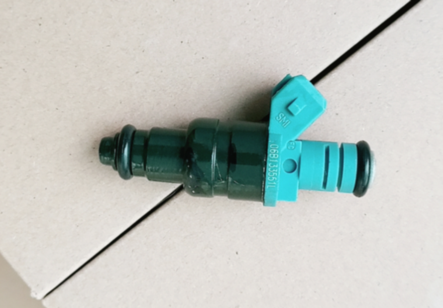
VAG 06B133551L INJECTOR,FUEL
Product Specifications
| VAG | 06B133551L |
| VAG | 06B133551C |
The INJECTOR,FUEL is an electromagnetic or piezoelectric fuel injector that delivers a precisely metered, finely atomised fuel spray into the engine's intake port or combustion chamber at the exact crank angle, duration, and spray geometry commanded by the ECU on every engine cycle, enabling the accurate air-fuel ratio control that modern combustion management, emissions compliance, and fuel economy targets require. Port fuel injection (PFI) injectors are mounted in the intake manifold and spray fuel against the back of the intake valve, where heat from the valve surface assists vaporisation before the charge enters the combustion chamber; the injector body contains a solenoid-operated needle valve held closed by a return spring at rest and opened by energising the solenoid winding, which lifts the needle off its seat and allows fuel from the pressurised common rail to flow through the precision-drilled spray holes in the nozzle plate; the spray pattern, droplet size, and cone angle are determined by the nozzle hole geometry — typically 4–12 holes of 0.15–0.25 mm diameter in a spray pattern optimised for the specific port geometry. Direct injection (GDI/FSI/TGDI) injectors mount directly in the combustion chamber and spray fuel at pressures of 100–350 bar directly into the compressed air charge, requiring a piezoelectric or multi-stage solenoid actuator capable of millisecond response times and multiple injection events per cycle. Both types depend on precise spray angle, fuel flow rate linearity, and valve seating integrity for correct combustion — a single cylinder's injector that flows 5% more or less than specification produces a cylinder contribution imbalance that manifests as rough idle, misfire, and emissions non-compliance.
This unit — VAG 06B133551L — is manufactured to OEM-equivalent specifications: static flow rate at rated fuel pressure, dynamic flow linearity across the ECU pulse width range, spray pattern cone angle and droplet size distribution, solenoid winding resistance, O-ring groove dimensions for rail and manifold sealing, electrical connector pinout, and overall body dimensions for the specific rail or manifold mounting position are matched to the original part. Supplied individually as a direct replacement for standard fitment. Available wholesale from 7.98 USD, MOQ 10 pcs, production lead time 5-7 days.
Fuel injectors fail through nozzle hole deposit formation — carbon and lacquer from combustion and fuel degradation that accumulates on the nozzle tip and spray holes, narrowing the orifice area and distorting the spray pattern; through solenoid winding open or short circuit from thermal cycling or insulation breakdown; through needle valve seat wear or deposits that prevent the valve from seating fully on ECU de-energisation, causing the injector to dribble fuel continuously and enrich the mixture with hydraulic leak-down; and through O-ring seal degradation that causes fuel leakage at the injector body sealing points. Deposit formation and flow rate drift are the most common failure modes and often affect all injectors on an engine simultaneously from the same fuel quality and operating condition exposure.
- Depressurise the fuel system before removing any injector — on PFI systems locate the fuel pump fuse or relay and crank the engine for 5–10 seconds with it removed to consume the residual rail pressure; on GDI systems the high-pressure circuit retains up to 350 bar when the engine is off and requires the engine to be cranked at idle for 30 seconds with the high-pressure pump fuse removed to bleed the rail pressure; never loosen an injector connector or rail clamp on a pressurised fuel system.
- Replace both O-rings — upper rail O-ring and lower manifold or combustion chamber seal — simultaneously with every injector replacement — the O-rings are single-use compression seals that take a permanent set to the groove geometry of the old injector; fitting new O-rings on the new injector body ensures correct sealing geometry; lubricate new O-rings with clean fuel or the specified O-ring lubricant before installation — never use petroleum grease which swells most fuel-system O-ring compounds.
- Clean the injector bore in the fuel rail and intake manifold or cylinder head before installing the new injector — carbon deposits from combustion gases that enter the injector bore during suck-back between injection events accumulate in the bore over time and prevent the new injector from seating correctly at its designed depth; use a wooden or plastic pick to remove any deposit ring at the bore rim before inserting the new injector.
- Insert the new injector straight into its bore and press firmly and evenly until the O-ring seats fully — twisting the injector during insertion rolls and damages the O-ring; align the injector's electrical connector in the correct orientation for the wiring harness before pressing home; confirm the injector is at its correct seating depth by checking that the fuel rail connector clip or clamp engages correctly — an injector seated at incorrect depth will show a gap at the rail clamp or will not allow the clamp to lock.
- After installation, cycle the ignition on and off three times without cranking to prime the fuel rail and pressurize the system; then inspect all injector positions for fuel odour or visible seepage before starting the engine; a leaking O-ring will produce a fuel smell detectable before the engine is running; address any seepage before the first start.
- Install the new INJECTOR,FUEL (VAG 06B133551L), start the engine and allow to idle, perform a cylinder contribution test on the scan tool confirming the replaced cylinder now matches the contribution of the other cylinders, clear all misfire and fuel trim codes, confirm no fuel odour at the injector area, and road test under varying load conditions confirming smooth acceleration and correct fuel economy before returning the vehicle to service.
| Part | Reason for Combined Replacement |
|---|---|
| Fuel Injector O-Ring Kit Upper and lower seals — application-specific compound | Both O-rings at every injector position must be replaced simultaneously with the injector — upper rail O-rings that have taken a compression set to the old injector's groove geometry will not seal correctly on the new injector body of even the same nominal diameter; lower manifold or combustion chamber seals that have been heat-set in the old injector's bore will not maintain sealing pressure at the new injector's slightly different tolerance stack. Always source the correct O-ring compound — fluorosilicone or Viton for high-temperature GDI positions; standard NBR for PFI applications. |
| Fuel Filter In-line or in-tank — OEM ref. varies | Injector flow rate reduction from deposit formation is accelerated by degraded fuel with elevated particulate or varnish content that passes through an overdue fuel filter. Replacing the fuel filter simultaneously with the injectors eliminates a primary contamination source that would begin degrading the new injectors' nozzles from the first fuelling. On vehicles with an accessible in-line fuel filter, include it in every injector replacement job. |
| Spark Plugs OEM specification — complete engine set | Injectors that have been operating in a flow-reduced state subject the spark plugs on the affected cylinders to a lean combustion environment that produces abnormally high combustion temperatures and accelerates electrode erosion. Inspecting the spark plugs when the injectors are replaced allows simultaneous assessment of each cylinder's combustion health — a plug with a white blistered insulator confirms sustained lean operation from a low-flow injector; plugs showing this condition should be replaced simultaneously with the injectors to restore the complete combustion system. |