VAG 03E103201C MEMBRANE
Product Specifications
| VAG | 03E103201C |
| VAG | 03E103765C |
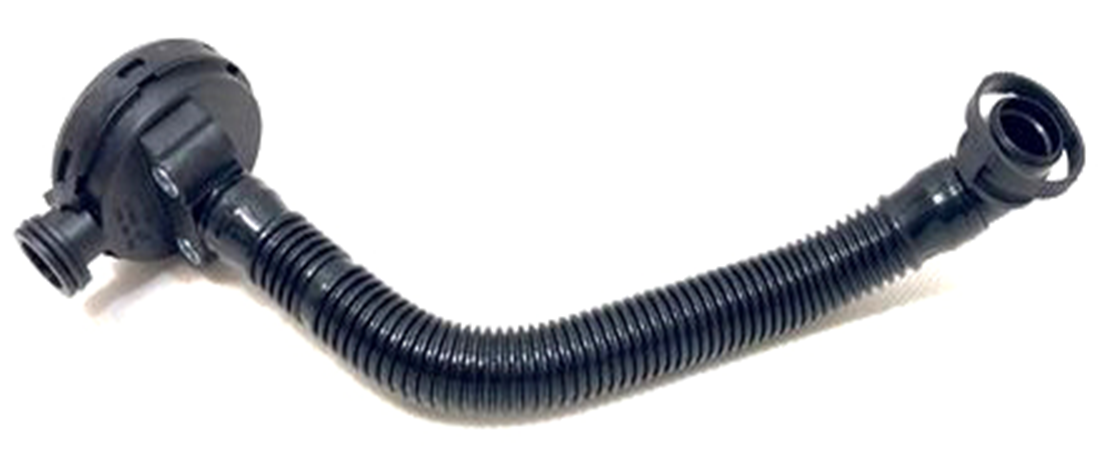
The MEMBRANE is the valve cover PCV membrane — a precision-moulded rubber or fibre-reinforced elastomer diaphragm integrated into the positive crankcase ventilation (PCV) valve assembly housed in or on the valve cover, that regulates the flow of crankcase blowby gases from the crankcase to the intake manifold by deflecting under differential pressure to open or restrict the gas flow path, maintaining the correct crankcase pressure within the designed operating range across all engine speed and load conditions. The membrane forms the active element of the pressure-regulating PCV valve: at idle and light load, high intake manifold vacuum is applied to one face of the membrane, causing it to deflect and partially close the blowby gas flow orifice, preventing the high vacuum from drawing excessive oil mist from the crankcase into the intake manifold; under high engine load when manifold vacuum is low, the membrane relaxes and allows maximum blowby gas flow through the PCV circuit, maintaining the crankcase at a slight negative pressure relative to atmosphere that prevents pressure-driven oil leakage past gaskets and seals. On many modern direct-injection and turbocharged engines the PCV membrane is integrated into a multi-chamber oil separator assembly on the valve cover that also incorporates a labyrinth oil mist separator — the blowby gas passes through the separator before reaching the membrane, depositing oil droplets on the separator baffles that drain back to the sump, so that only deaerated gas continues through the membrane to the intake.
This unit — VAG 03E103201C — is manufactured to OEM-equivalent specifications: membrane outer diameter and seating bead geometry for the PCV valve housing, membrane thickness and durometer for the designed pressure-flow regulation characteristic, material compound — fluorocarbon rubber (FKM) or hydrogenated nitrile (HNBR) — for resistance to blowby gas chemistry at 100–130°C operating temperature, and overall assembly dimensions for valve cover integration are matched to the original part. Supplied as a replacement membrane element or as a complete PCV valve assembly depending on application. Available wholesale from 7.97 USD, MOQ 100 pcs, production lead time 20-45 days.
PCV membranes fail through rubber hardening and cracking from sustained exposure to blowby gas at elevated temperatures — a hardened membrane loses its elasticity and can no longer deflect proportionally to regulate crankcase pressure, either sticking open and causing excessive oil consumption from over-ventilation, or sticking closed and allowing crankcase pressure to build until it forces oil past seals and gaskets; through perforation from fuel dilution of the crankcase oil in direct-injection engines that washes unburned fuel past the rings and chemically attacks the membrane compound; and through membrane tearing from overpressure events when the engine has been cranked with a blocked crankcase breather circuit.
- Clean the PCV valve housing bore and the membrane seating recess thoroughly before installing the new membrane — oil varnish and soot deposits on the housing bore prevent the new membrane from seating uniformly in its recess, creating a leak path around the membrane edge that bypasses the membrane's pressure-regulating function; use brake cleaner and a cotton swab to clean the seating recess and confirm the housing bore is free of raised deposits that would prevent the membrane from lying flat.
- Inspect the oil separator baffles and labyrinth passages in the valve cover for oil sludge accumulation before reassembly — a failed membrane that has been drawing oil mist through the PCV circuit may have deposited sludge in the oil separator passages, restricting gas flow to the membrane even after the membrane is replaced; flush the separator passages with brake cleaner from the PCV outlet port and confirm free airflow through all passages before installing the new membrane.
- Confirm the correct orientation of the membrane before seating it in the housing — PCV membranes are asymmetric; one face bears against the flow orifice seat and the other faces the pressure differential that deflects the membrane; installing the membrane inverted reverses the pressure response and causes the membrane to open under high vacuum rather than restricting, producing maximum oil mist draw from the crankcase at exactly the engine conditions where it should be minimised; confirm the correct face orientation from the OEM service documentation or from the membrane's moulded reference marking.
- Replace the complete PCV valve assembly rather than the membrane element alone on applications where the membrane is press-fitted into a plastic housing — on many engines the PCV valve is a sealed plastic assembly that cannot be disassembled without damaging the housing; attempting to lever out the old membrane deforms the plastic housing bore and prevents the new membrane from seating correctly; the complete valve assembly replacement ensures the housing bore geometry is undamaged and the new membrane seals correctly at its designed seating pressure.
- Flush and clean the PCV hoses connecting the valve cover to the intake manifold and to the air filter housing before reconnecting them to the new membrane assembly — a failed membrane that passed oil into the PCV circuit will have deposited oil varnish inside the PCV hoses; this varnish restricts hose flow area and can shed deposits that block the new membrane's flow orifice; flush each hose individually with brake cleaner and blow through with compressed air before reconnecting.
- Install the new MEMBRANE (VAG 03E103201C), reconnect all PCV hoses, start the engine and perform the crankcase pressure test by pressing a clean cloth against the oil filler neck — the cloth should be drawn gently inward confirming negative crankcase pressure; confirm no lean mixture codes after a full warm-up cycle; perform an oil level check after 500 km to confirm oil consumption has been eliminated before returning the vehicle to service.
| Part | Reason for Combined Replacement |
|---|---|
| Valve Cover Gasket OEM ref. varies by engine | The valve cover is removed to access the PCV membrane on most applications where the membrane is integrated into the valve cover PCV valve housing. With the valve cover removed, the valve cover gasket is fully exposed and its condition can be assessed directly — a gasket showing compression set or oil seeping indicates it should be renewed simultaneously with the membrane. The combined labour for valve cover removal is already expended; renewing the gasket at this point eliminates a repeat valve cover removal for a gasket leak within a short interval. |
| Breather Hose and PCV Hose Set OEM ref. varies by engine PCV routing | The breather hoses connecting the valve cover PCV outlet to the intake manifold and air filter housing are subject to the same oil mist and blowby gas environment that degraded the membrane. Hoses that have been carrying oil-contaminated gas from a failed membrane will have internal varnish deposits and may have hardened rubber ends that no longer seal at the connection stubs. Replacing the hoses simultaneously with the membrane ensures the complete PCV circuit is restored to clean, correctly sealed condition. |
| Engine Oil and Filter Grade and specification per OEM requirement | A PCV membrane that has failed closed has been trapping combustion by-products — water, nitrogen oxides, partially burned fuel — in the crankcase oil, significantly accelerating the oil's chemical degradation. An oil that has been contaminated by trapped blowby products will have elevated acidity and reduced anti-wear additive concentration regardless of its age in kilometres. Perform a complete oil and filter change simultaneously with membrane replacement to remove the degraded oil and restore the engine's lubrication system to correct chemistry from the first post-repair operating cycle. |