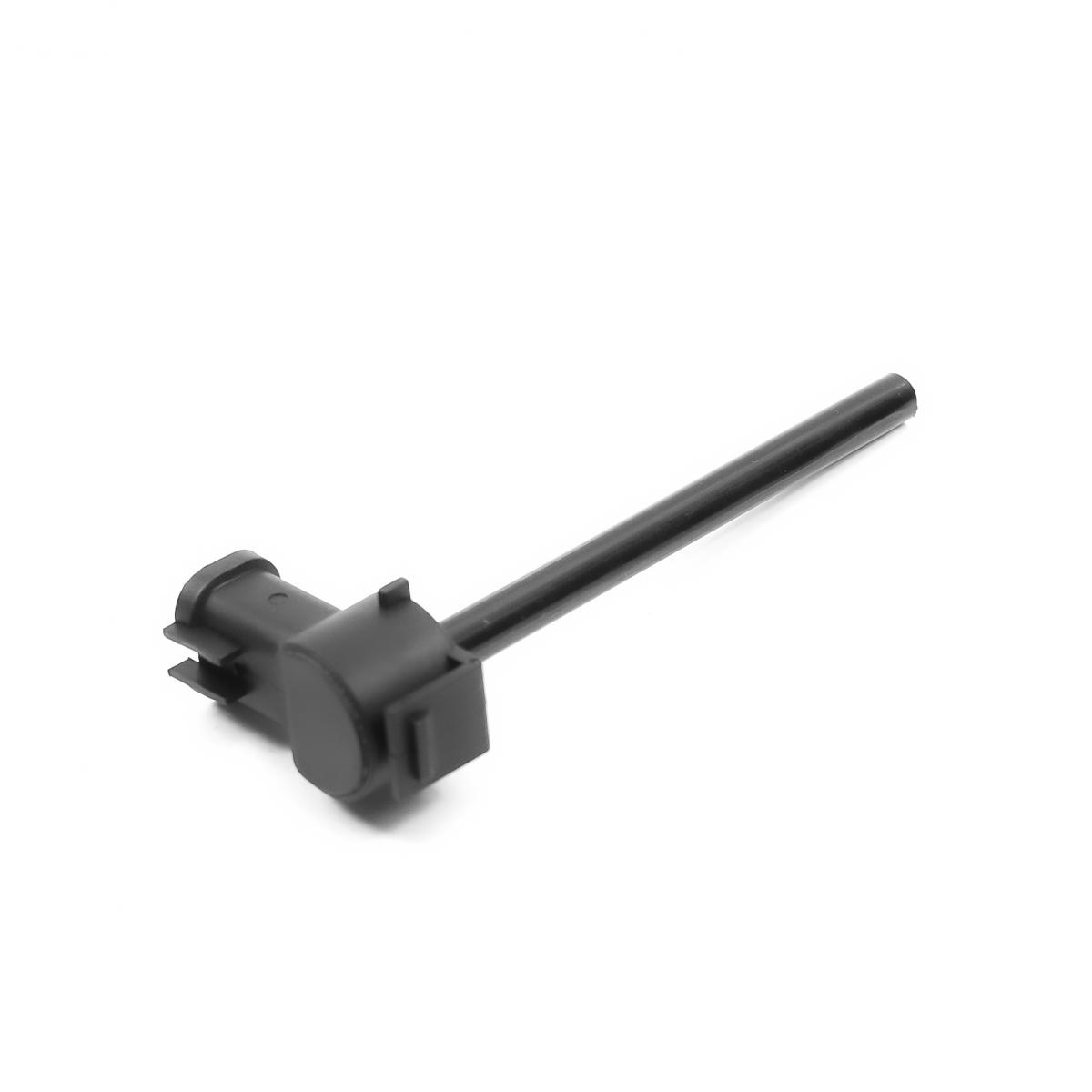
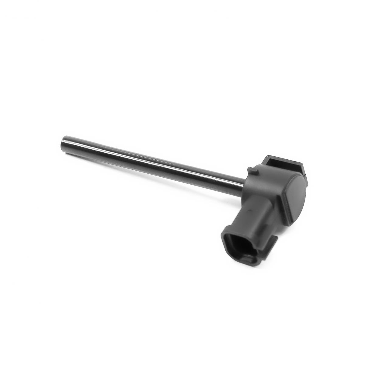
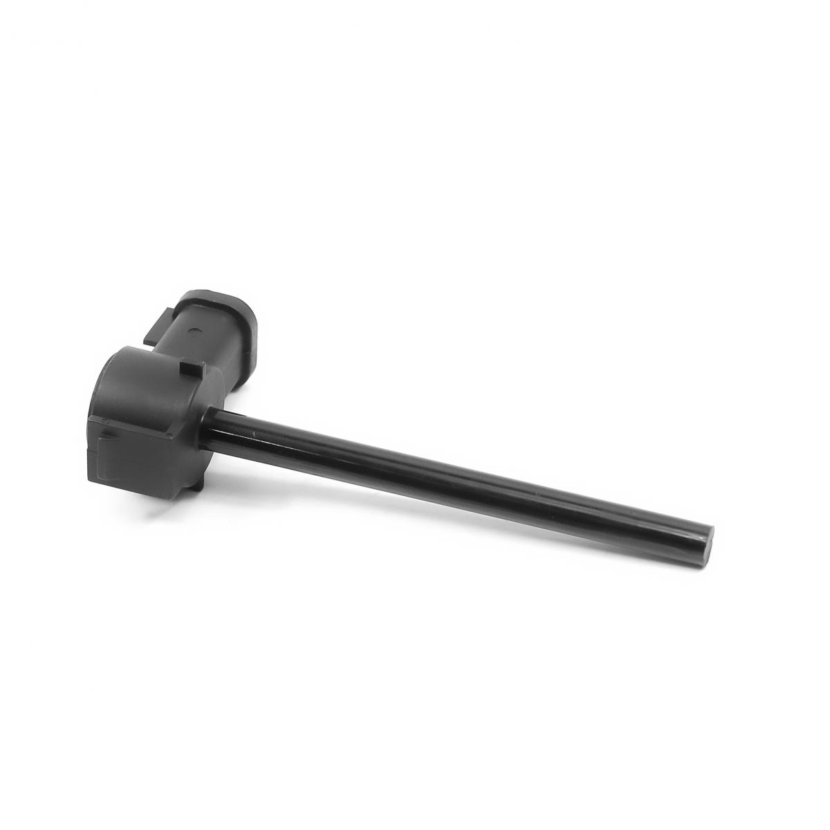
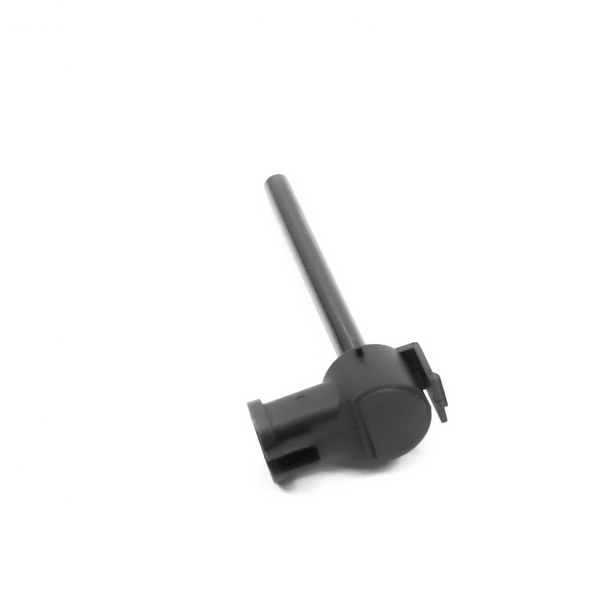
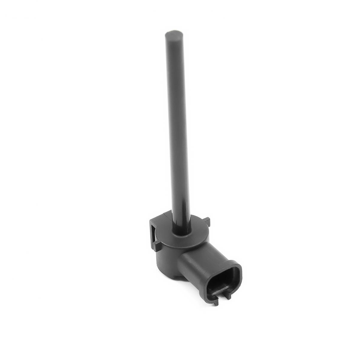
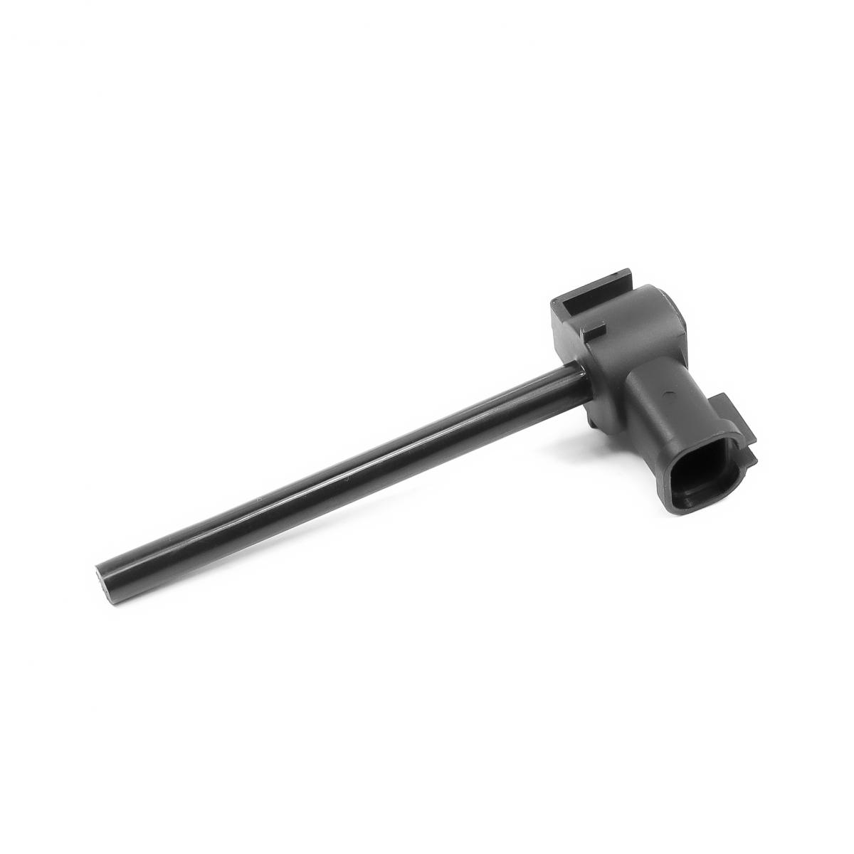
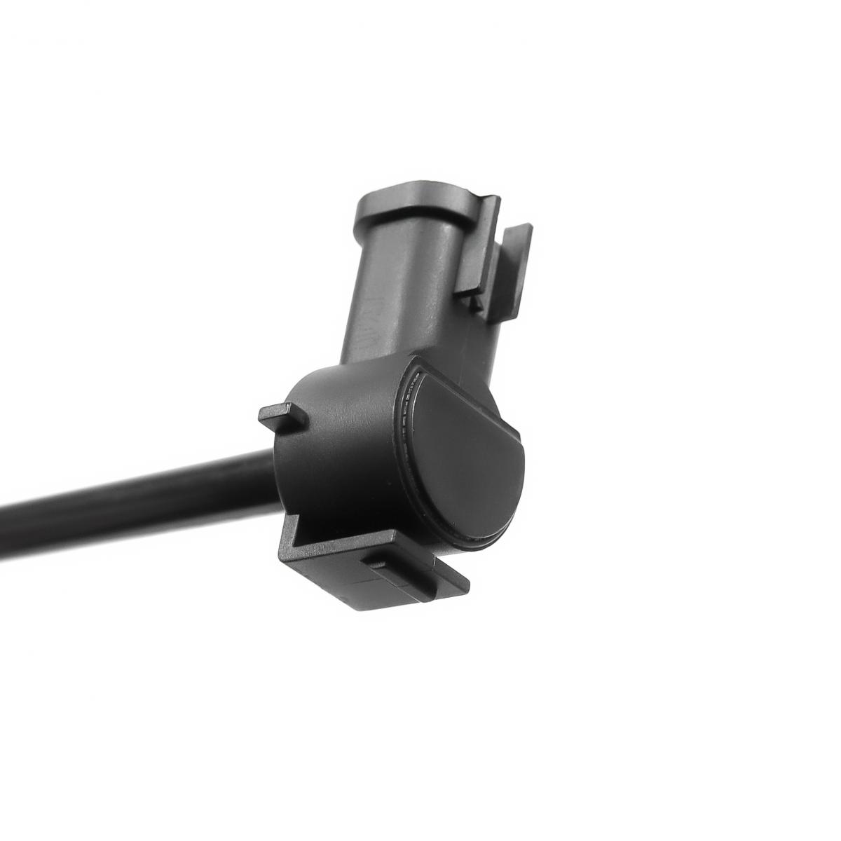
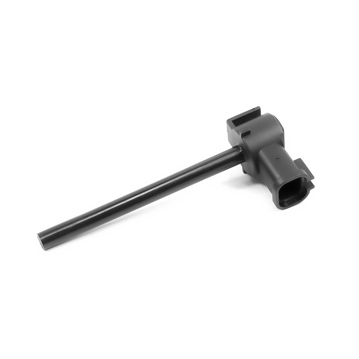
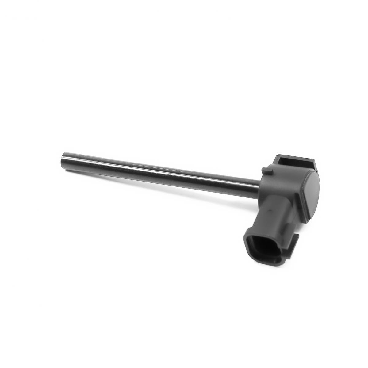
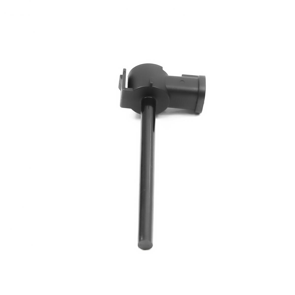
QUATTRO FRENI QF25A00101 COOLANT LEVEL SENSOR
Product Specifications
| MAN | 81274210232 |
| MAN | 81274210195 |
| MAN | 81274210264 |
| QUATTRO FRENI | QF25A00101 |
The coolant level sensor is a liquid-level monitoring component used in automotive and commercial vehicle engine cooling systems. It detects the presence and height of coolant within the expansion tank or reservoir and converts this information into an electrical signal for the vehicle control module. This signal allows the engine management system or instrument cluster to determine when coolant levels fall below safe thresholds and trigger warning indicators to protect the engine from overheating and potential damage.
The sensor typically uses a float mechanism with magnetic reed switches or a thermistor-based level detection system. In float-type sensors, a buoyant element rises and falls with the coolant level, actuating magnetic switches at specific heights to signal low, normal, or critical levels. In thermistor-type sensors, heating elements are positioned at different heights; when coolant level drops below a sensor element, the element heats up differently, creating a measurable change in electrical resistance that indicates low coolant condition. The sensor is installed in the coolant expansion tank or reservoir, positioned to detect when coolant volume has decreased to a point where cooling system efficiency may be compromised.
By continuously monitoring reservoir coolant level, the system provides early warning of low fluid conditions that may result from leaks, evaporation, or system malfunction. This early detection prevents reduced cooling efficiency, localized overheating, air pocket formation in the cooling circuit, and potential catastrophic engine damage from coolant loss. A functional coolant level sensor is particularly critical in commercial vehicles where extended operation, heavy loads, and harsh conditions increase the risk of cooling system stress. The sensor helps maintain proper thermal management by ensuring the cooling system operates with adequate fluid volume and alerts the driver of fluid loss before critical temperature thresholds are reached, allowing for timely intervention and preventing expensive engine repairs.
Common Failure Symptoms
- Low coolant warning light or message displayed on the instrument cluster despite coolant level being within normal operating range
- Low coolant warning does not appear when coolant level is actually low or critically low
- Coolant level warning activates intermittently, flickering, or behaving erratically during driving or after engine start
- Warning activates only during certain driving conditions such as cornering, acceleration, or rough road surfaces
- Cooling system warning behavior is unstable or inconsistent after engine start or during normal operation
- False warning messages related to coolant system requiring investigation or service
Diagnostic Approach
When diagnosing coolant level sensor issues, begin by visually inspecting the actual coolant level in the expansion tank with the engine cold. Compare the actual level to the minimum and maximum marks on the tank. If the level is normal but the warning is active, suspect sensor failure. Inspect the sensor and wiring connector for corrosion, damage, contaminated contacts, or moisture intrusion. Check the connector pins for bent or corroded terminals. Use a multimeter to test sensor continuity or resistance according to specifications in the service manual (resistance values vary by sensor type). For float-type sensors, gently move the float mechanism to verify it moves freely without binding. Check for debris, sludge, or coolant residue buildup on the sensor that might interfere with float operation. Inspect the expansion tank for cracks, damage, or contamination that might affect sensor operation.
Product Classification
| Product Type | Liquid level sensor for automotive cooling system |
| HS Code | To be confirmed by customs broker |
| Country of Origin | China |
| Manufacturer | QUATTRO FRENI |
| Hazardous Goods | No |
Available for wholesale distribution with bulk order support. International shipping via express courier, air freight, or sea freight. Common Incoterms (EXW, FOB, CIF) available upon request. Export documentation provided.
The following table lists verified OEM cross-references and confirmed vehicle applications for MAN part numbers 81274210232 and 81274210195 based on multiple independent commercial vehicle parts sources.
| Model Series | Years | Vehicle Type | OEM Numbers |
|---|---|---|---|
| MAN F 2000 | 1994–2005 | Heavy Truck | 81274210232 / 81274210195 |
| MAN TGA | 1999–2014 | Heavy Truck | 81274210232 / 81274210195 |
| MAN TGS | 2005+ | Heavy Truck | 81274210232 / 81274210195 |
| MAN TGX | 2006+ | Heavy Truck | 81274210232 / 81274210195 |
| NEOPLAN Tourliner | 2002+ | Coach / Bus | 81274210232 / 81274210195 |
| MAN Bus Series | Various | Bus / Coach | 81274210232 / 81274210195 |
- Prepare vehicle and cool system: Park on level ground and engage parking brake. Allow the engine to cool completely (at least 2 hours after operation) to prevent burns from hot coolant. Never open the cooling system when hot.
- Relieve system pressure: Slowly loosen the expansion tank cap to the first detent position to release any residual pressure. Wait for hissing to stop, then fully remove the cap. Be prepared for minor coolant spillage.
- Drain coolant (optional): For easier installation, partially drain coolant by opening the radiator drain valve or removing the lower radiator hose. Drain into a clean container for reuse if coolant is fresh and uncontaminated. Dispose of old coolant according to local environmental regulations.
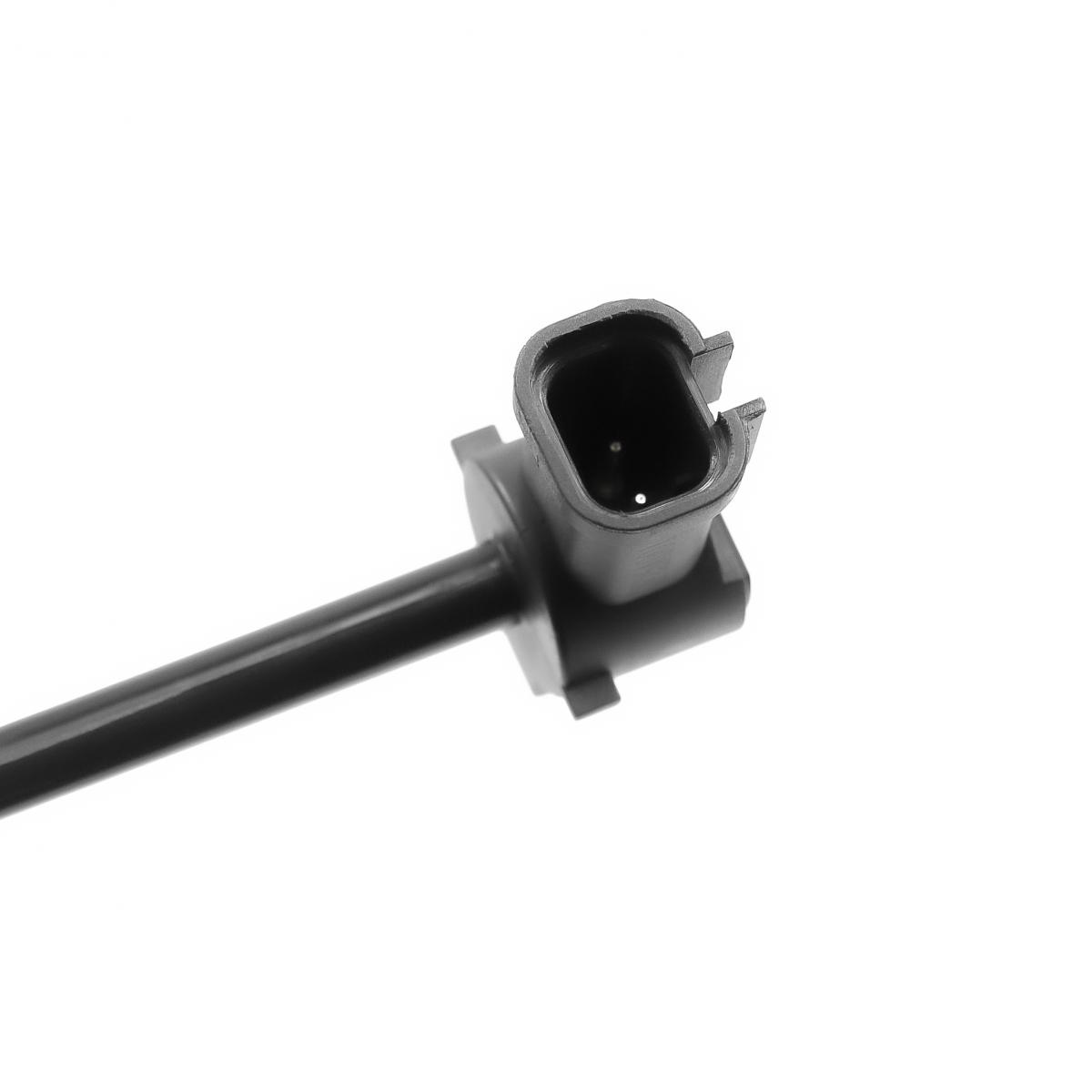
- Disconnect electrical connector: Locate the sensor on the expansion tank. Press the release tab and carefully disconnect the electrical connector. Inspect the connector and pins for corrosion, damage, or moisture. Clean terminals with electrical contact cleaner if necessary.
- Remove old sensor: The sensor typically has a quarter-turn bayonet mount or threaded connection. Rotate the sensor counterclockwise (usually 90 degrees for bayonet type) and pull straight out. Some sensors may have a retaining clip that must be released first. Be prepared for coolant spillage; have rags ready.
- Clean installation area: Clean the sensor mounting hole in the expansion tank thoroughly. Remove any debris, sludge, crystallized coolant deposits, or old gasket material using a lint-free cloth. Inspect the tank for cracks or damage.
- Install new sensor: Install the new O-ring or gasket if included (do not reuse old seals). Lightly lubricate the O-ring with clean coolant. Insert the sensor into the mounting hole and rotate clockwise (for bayonet type) until it locks into place with a positive click. For threaded sensors, hand-tighten then use a wrench to snug (do not overtighten; typical torque 5-8 Nm).
- Reconnect electrical connector: Reconnect the sensor connector and ensure it clicks securely into place. Verify the connector lock tab is engaged. Secure any wiring harness clips.
- Refill coolant system: Refill the expansion tank with proper coolant mixture (typically 50/50 antifreeze and distilled water or pre-mixed coolant to manufacturer specification). Fill to the maximum mark with engine cold. Install and tighten the expansion tank cap.
- Bleed air and test: Start the engine and allow it to warm up to operating temperature with the heater on maximum. Monitor coolant level and add as necessary to compensate for air evacuation. Check for leaks around the sensor. Verify the coolant warning light operates correctly (it should illuminate briefly at key-on then extinguish). Test by lowering coolant level below minimum mark to verify warning activates.